Chapter 11. Screens and Flow Options
Screen technology is one of the most powerful yet extremely misunderstood features that is part of the SRX, and it has been around since the NetScreen days. As an engineer who has seen countless deployments, many implementations of Screens are not properly tuned or understood by customers. With all of the advanced Layer 7 threats present in modern-day networking, it is very easy to overlook Layer 3 and Layer 4 threats. The truth is that although the main source of Internet threats has shifted to Layer 7 over the past decade, Layer 3 and 4 threats are still every bit as pertinent and potent, especially if you do not have adequate defenses against them.
At this point you might be asking yourself, what exactly are Screens? A Screen is a Layer 3 or Layer 4 IPS setting that can be used to detect and block various anomalies and set certain thresholds for activities at those layers. They are effective at blocking such Layer 3 and Layer 4 DoS attacks that are still perpetrated every day with great effectiveness. Examining the headlines over the last few years regarding well-known hacking, political, cybercrime, and military organizations, you will discover numerous instances of Layer 3 and Layer 4 DoS attacks that are extremely effective, in addition to those that take place at Layer 7.
In this chapter, we are going to dissect the Screen technology piece by piece. We explore how the different Screens function, where they are implemented, how they should be deployed, and how to effectively tune them for maximum effectiveness.
Additionally, we explore some of the flow configuration options supported by the SRX that often complement the many Screens to not only enforce network behaviors, but also prevent some DoS vectors. By the end of this chapter, you should have a high degree of confidence in deploying Screens and flow options properly so that they can be effective before a DoS attack, rather than learning this information in hindsight (as is often the case with many organizations).
A Brief Review of Denial-of-Service Attacks
Before examining the Screen technology at length, it is important to review the challenge that this technology solves to gain a proper understanding of how to apply it. Most security specialists are quite familiar with the concept of a DoS attack at a high level, particularly with all of the notoriety given to many modern attacks against well-known institutions in the last few years. Still, there is a bit more analysis that must be done when considering Screens. For the purpose of this chapter, we break up DoS attacks into two categories: exploit based and flood based.
Exploit-Based DoS
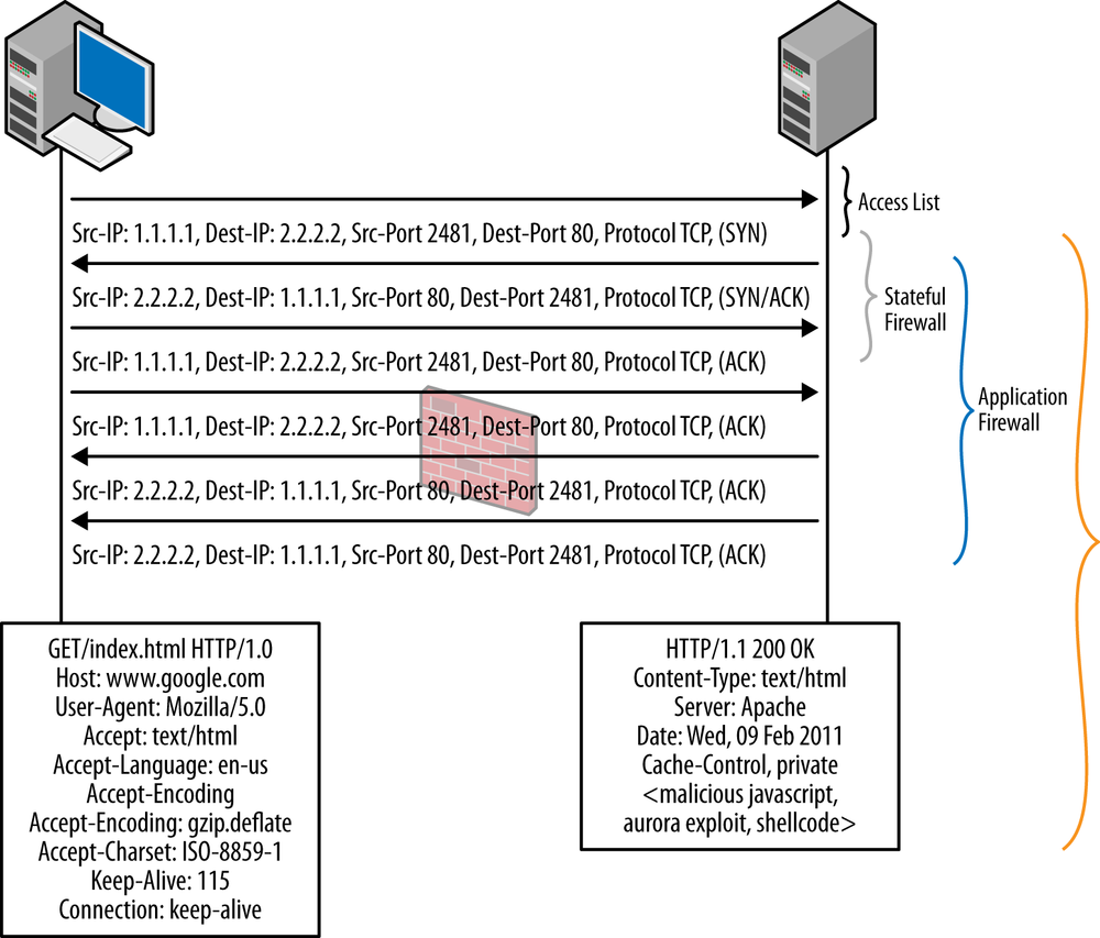
An exploit-based DoS attack (see Figure 11-1) is one that exploits a particular software vulnerability to create a system or service outage. The outage could cause the service to become completely unavailable or just unavailable during the attack itself. Typically, exploit-based attacks are not high-volume attacks, but rather cause the system to become unstable in one form or another due to a vulnerability. It’s important to remember that not all vulnerabilities lead to a compromise of the victim system giving the attacker control; it all depends on the nature of the vulnerability and several other factors about the vulnerable code to determine if one can actually compromise the system. Often one might find a vulnerability that cannot (feasibly) be compromised to give the attacker control, but could still make the system unstable by overwriting some memory with random data and causing a segmentation fault or some other unpredictable execution. We consider these to be exploit-based DoS attacks because they attack a specific vulnerability. Exploit-based attacks are not the primary focus of Screens, as this is something that is much more effectively covered by IPS and is discussed in Chapter 13.
Flood-Based DoS
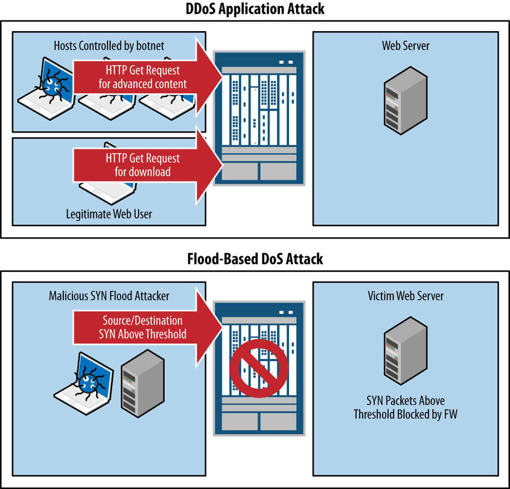
A flood-based DoS attack is very different from an exploit-based DoS attack in virtually every way, as shown in Figure 11-2. Unlike the exploit-based DoS attack, which exploits a vulnerability in the victim system, a flood-based DoS attack overwhelms the victim system with legitimate traffic—although at an anomalous rate—leaving the victim system unavailable. Sometimes the effects of the attack will only be felt while the attack is underway, but other instances will leave the system overwhelmed and cause it to crash completely, requiring manual intervention to restart it. In fact, many security and application engineers will likely have stories of such attacks (or misconfigurations like a bridge loop) not only bringing a system offline, but actually corrupting the filesystem or applications.
Flood-based DoS attacks can take many forms, which we discuss in this chapter. Some of the common attacks would include SYN floods, UDP floods, ICMP floods, and IP packet floods, which serve to overwhelm the victim system. Often, without adequate protection, not only can the end systems be victimized, but so can the intermediate networking devices, especially those that operate at Layer 4 and above. It is therefore very important to keep this in mind for virtually every firewall deployment.
Note
There is technically a hybrid of a flood + exploit DoS attack, which exploits a vulnerability that consumes more CPU cycles than a standard operation, but in and of itself won’t cause a DoS scenario. Instead, this attack must be flooded over multiple sessions to create a cumulative effect. Some examples of this type of attack include CVE-2011-3192 against Apache and CVE-2011-1473 against OpenSSL.
DoS Versus DDoS
If you’re somewhat unfamiliar with this category of attacks, it is helpful to classify what a DoS versus a DDoS attack is. A DoS is a denial-of-service attack in general, but it does not specify the magnitude of sources. A distributed denial-of-service attack is coordinated by a large number of sources (hundreds, thousands, or even millions). Typically, these attacks are launched by an individual or organization that controls the attacking hosts through a botnet. This attack produces a coordinated effect that is much more difficult to deflect than an attack from an individual hacker, which can be surgically blocked from a source IP address perspective. For the purposes of this chapter, DoS and DDoS can be used relatively interchangeably, and Screens are just as effective for protecting against DDoS as they are DoS to the limits of the platform.
Note
Screen functionality is primarily for Layer 3 and Layer 4 DoS/DDoS protection, but do not provide DDoS protection at Layer 7. Although Screens are still a critical technology to deploy even if concerned with L7-based DDoS attacks, to provide complete coverage Screens should be used in conjunction with a Layer 7 anti-DDoS technology. In 2013, Juniper acquired Webscreen Technologies and their appliance/VM-based DDoS solution. This has been rebranded as Junos DDoS Secure. This solution should definitely be examined to provide protection against Layer 7 DDoS attacks.
Screen Theory and Examples
Now that we’ve examined some of the threats that lead to the need for a Layer 3 and Layer 4 DoS solution, let’s dive deeper into the threats, technologies, and examples. For this section, we are going to explore several facets of Screens, so it is helpful to break them down into digestible segments for each type of attack. We explore each type of attack and how Screens can be applied.
Note
With the emergence of IPv6 in modern networks, it is only logical that these same attacks can be perpetrated on IPv6 as well as IPv4. The good news is that the SRX provides protection for both IPv4 and IPv6 with Screens. There are a few exceptions with the IP packet Screens which only apply to IPv4, including the Security Option and Loose/Strict Route Options which don’t apply to IPv6. But for the most part, Screens provides similar capabilities for IPv6 by default when IPv6 processing is enabled.
How Screens Fit into the Packet Flow
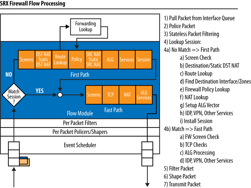
So far, we have discussed in general what Screens do, but we haven’t explained why they are so effective at protecting both end systems along with the firewall itself. Screens are so effective because they are lightweight, and more important, they are processed as early in the flow chain as possible. This means that before we start going through the effort of setting up a session or fully examining the packet for protocol state, we apply the Screens, so that packets can be dropped as early in the process as possible. Figure 11-3 shows where the Screens are applied. Note that the packet-based Screens are always applied regardless of whether the session is established, whereas other Screens are only applied at session inception. We explain how this works on a Screen-by-Screen basis later in this chapter.
Screen Processing only happens on the ingress interface
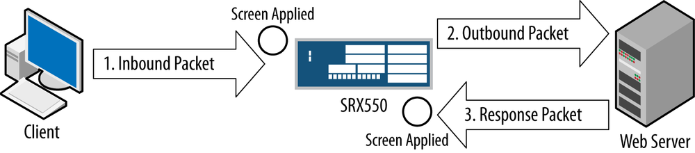
It is very important to understand that Screens are only applied when the packet arrives on the SRX, not at any other point in the packet flow. This is because we want to deny an offense as soon as it arrives on the SRX rather than process the packet only to drop it later for some violation. It’s important to remember that Screens are only processed on the ingress, so when you consider where to enable a Screen, it should always be on the zone on which the packet arrives. Screens don’t have a concept of from- and to-zones; they are processed on a zone-by-zone basis when they arrive on an interface, as shown in Figure 11-4.
Note
At the time of writing this book, the SRX does not support applying Screens to tunnel interfaces, only to IFL interfaces like ge-0/0/0.0. This might change in the future, so check the current release notes and documentation for the current status.
Screens in Hardware and Software
Another factor that makes Screens so effective is that on the high-end SRX platforms, most of them are done in hardware on the NPU, so that the platform can essentially process the Screens at line rate. All of the packet-based Screens along with the flood-based Screens are handled in the NPUs. The only Screens that are not done in the NPU are those that require some additional state tracking across the entire box. For instance, IP Session Limits, TCP/UDP Sweep, and Port Scan Screens must be done in a combination of the CP and SPU because not all packets flow through a single NPU or SPU (unless that is the only NPU or SPU in the platform). The CP has a master list of the sessions and is aware of the sessions that exist on the platform, so it can effectively determine whether the limits have been violated. It is important to note that even in this case, these Screens are performed well after the initial packet and flood-based Screens are performed to better protect the platform.
The branch SRX always processes Screens in software in the central processor, but they are all done on the data plane and not on the control plane, so the platform should still be able to remain available in the face of a DoS attack (particularly if you are using fxp0 for out-of-band management rather than an in-band revenue interface). Screens are quite effective for the branch SRX, but if you are truly concerned about massive DoS attacks, you should really consider an SRX high-end platform.
As mentioned, all Screens and other data processing is done on the data plane and not on the control plane. This means that the platform should still remain available for management even in the event that it comes under a massive attack that reaches the limits of the platform.
Note
It’s a best practice to not leave flow debugs or packet captures enabled when not in a specific troubleshooting case, as these messages are sent to the RE, so it can affect performance and result in availability issues if you were under a DoS attack.
Screen Profiles
Before we dive into the plethora of Screens and the various options for configuring them, it is important to understand how Screens are applied and enforced on the SRX. In the SRX, Screens are essentially configured as profiles that are applied at the zone level; that is, Screens can be applied on a zone-by-zone basis to provide the firewall administrator with the ability to define different thresholds and limits on a zone-by-zone basis. This is very important, because often, an administrator will want to configure different limits on the external-facing zone, where DoS threats are the most likely, rather than the internal segments where more control of users is possible. That isn’t to say you shouldn’t configure Screens on an internal zone, because we know that even the resources of an organization can become infected with malware that could participate in a DoS attack toward the Internet or consume unnecessary resources. The point is that you have the ability to apply different thresholds for the different zones to complement the varying security posture of each segment that connects to the firewall.
Packet versus threshold Screens
Screens can be broken down into two different types: packet-based Screens and threshold-based Screens. Packet-based Screens are evaluated on a packet-by-packet basis in a stateless fashion. For instance, the SYN-FIN Screen checks each packet to see if the TCP packet has both the SYN and FIN bits set, which is clearly illegal. This is done on a packet-by-packet basis without regard to other factors.
Threshold-based Screens, on the other hand, are applied in a semistateful fashion. The SRX must track the threshold on some basis within each zone (e.g., per source IP), and once the configured threshold is reached, an action will be taken. For instance, the SYN Flood Screen allows the administrator to define how many SYN packets can be sent from or to a source or destination. Any SYN packets below the threshold will be passed, but once the threshold is reached, any packets violating the limit will be dropped. Don’t worry about remembering the specific Screens here, as we will be covering each one in depth later in the chapter.
Applying Screen profiles to single and multiple zones
You can think of a Screen profile as an independent profile that can be applied to one or more zones. When a zone consists of multiple interfaces, a Screen is tracked at the zone level, with each interface contributing to the threshold-based Screens that can be triggered. On the other hand, when you have a Screen profile that is applied to multiple zones, each zone will be treated and tracked separately, so the profile is only the same from a configuration perspective.
Note
Just remember, when SRX configurations are applied to a zone, they affect the member interfaces collectively, but they are tracked separately from other zones just like any other zone-based setting.
Configuring a Screen profile
Screen profiles are defined under the Security Screen stanzas as a profile, which
is then applied at the zone level as discussed. This example
configures a Screen called Internet-Screen and will apply it to the
Internet zone:
root@SRX550-Node0# set security screen ids-option SRX Internet-Screen description "Screen Applied to the Internet Zone"
{primary:node0}[edit]
root@SRX550-Node0# set security zones security-zone Internet screen Internet-Screen
{primary:node0}[edit]
root@SRX550-Node0# show security screen
ids-option Internet-Screen {
    description "Screen Applied to the Internet Zone";
}

{primary:node0}[edit]
root@SRX550-Node0# show security zones
security-zone Internet {
    screen Internet-Screen;
}
Screen profiles only have one option (besides the
description), which is alarm-without-drop. This setting means that
a log or alarm will be triggered for the event, but no action will be
taken. This is a simple switch to turn Screen enforcement on and off
on a per Screen profile basis. It is useful when doing initial
deployments to ensure that you are not going to cause any adverse
impacts to the network.
Note
Among your fellow engineers, no doubt there are some battle stories about how some third party decided to write their own TCP/IP stack or behave in some anomalous fashion that simulates a suspicious behavior that such protections can break. Sometimes it helps to do a brief trial with Screens enabled before turning on enforcement to ensure there won’t be any adverse effects or that they can be investigated before taking action.
DoS Attacks with IP Protocols
In this section, we examine the plethora of IP protocol attacks that the SRX can defend against. Although many of these attacks are packet anomalies that might not be able to actually crash any modern OS, their presence on the network still should be viewed with suspicion. Additionally, although well-known modern OSs are not typically vulnerable to issues with the packet anomalies, the great expansion of mobile, tablet, and network-capable peripheral devices could well make them vulnerable. In the case of the mobile and tablet world, many OSs have not stood the test of time; network peripheral devices especially run very stripped-down OSs that are unlikely to have been fuzzed or pen tested with security analysis tools.
Bad IP Option Screen
Both IPv4 and IPv6 support a dynamic field called the IP Options field. This field contains a Type/Length/Value tuple that can be of variable length. The Bad Option Screen will drop any packets that are malformed due to incorrect IP options in the IP header.
Screen Type: Per-Packet
Screen Processing Location: NPU for high-end SRX, Forwarding Engine branch SRX
Configuring Bad IP Option Screen
The Bad IP Option Screen is very easy to configure as it is either on or off; there are no other options or considerations for enabling this Screen.
{primary:node0}[edit security screen]
root@SRX550-Node0# set ids-option Internet-Screen ip bad-option

{primary:node0}[edit security screen]
root@SRX550-Node0# show
ids-option Internet-Screen {
    ip {
        bad-option;
    }
}
Block Frag Screen
IP fragments are packets that have been divided from an original packet when the MTU of the link between a client and server can’t support the packet size somewhere along the path. The MTU for Ethernet is 1,514 (including the Level 2 header) meaning that the IP packet can be 1,500 bytes long. Sometimes when you are further encapsulating the packet in protocols like IPsec, GRE, PPPoE, and others that must still transmit over the same link MTU of 1,514, the packets might have to be split up. There are other cases when fragmentation can be used that are entirely legitimate.
In some cases, though, packet fragmentation can be used as an offensive technique both from a DoS perspective and also for evading Layer 7 devices, which might not properly parse the fragmented packets, especially when they come out of order or overlap. Packet fragmentation might be perfectly acceptable, but if there is no reason why packets should be fragmented, you can use this Screen to block them entirely when they arrive on the firewall.
Also remember that for IPv6, fragments are supported on routers; however, unlike IPv4, an IPv6 router will not do any fragmentation itself. It will drop any packet that is too large to send on the upstream/downstream media. Instead, IPv6 relies on a Path MTU ICMPv6 message to ensure that no fragmentation will need to happen elsewhere on the data path. The reason for this is because it can be taxing for routers to have to fragment the packets and, ideally, this shouldn’t be the router’s responsibility. This doesn’t mean that you need to enable the Block Frag Option in IPv6, but it is important to remember as the firewall will drop IPv6 packets that need to be fragmented, regardless of whether the Block Frag Screen is enabled or not.
Screen Type: Per Packet
Screen Processing Location: NPU for high-end SRX, Forwarding Engine branch SRX
Configuring Block Frag Screen
Configuring the Block Frag Screen is very easy, as it requires no additional options, just to be enabled for the Screen profile.
{primary:node0}[edit security screen]
root@SRX550-Node0# set ids-option Internet-Screen ip block-frag

{primary:node0}[edit security screen]
root@SRX550-Node0# show
ids-option Internet-Screen {
    ip {
        block-frag;
    }
}
Route Option Screens
Another set of IP option Screens are those of the IP Route Option family. There are four Route Option Screens that you can configure blocking on independently:
- Record Route Option
This option is to trigger the router to insert its IP address into the IP option field to inform the endpoint of the routers along this path. This can be used for recon purposes by an attacker.
- Loose Source Route Option
Source routing allows the source to define the path a packet should take. Loose source routing means that certain routes must be taken, but it is not necessarily the entire path. An attacker can use this to define the way a packet should traverse a network, potentially bypassing segments and transit devices. Normally, an attacker shouldn’t control the path. Source routing is not typical for modern networks.
- Strict Source Route Option
This route option defines the explicit path a packet should take through a network to reach the endpoint. Like the Loose Source Route Option, it is not a common option that should be enabled in modern networks.
- Source Route Option
This blocks any route option that is source route in nature, including loose and strict options.
Screen Type: Per Packet
Screen Processing Location: NPU for high-end SRX, Forwarding Engine branch SRX
Configuring Route Option Screens
Configuring Route Option Screens is simple; as they are either enabled or disabled, there are no threshold or other considerations. For this example, we enable all four Route Option Screens.
{primary:node0}[edit security screen]
root@SRX550-Node0# set ids-option Internet-Screen ip record-route-option

{primary:node0}[edit security screen]
root@SRX550-Node0# set ids-option Internet-Screen ip loose-source-route-option

{primary:node0}[edit security screen]
root@SRX550-Node0# set ids-option Internet-Screen ip source-route-option

root@SRX550-Node0# set ids-option Internet-Screen ip strict-source-route-option

{primary:node0}[edit security screen]
root@SRX550-Node0# show
ids-option Internet-Screen {
    ip {
        record-route-option;
        source-route-option;
        loose-source-route-option;
        strict-source-route-option;
    }
}
IP Security Option Screen
The IP Security Option is largely deprecated and probably will never be seen on any modern network for legitimate uses. Originally, it was an RFC developed by the US Department of Defense (791, 1038). It was never really implemented and is considered obsolete. It is best to block any packets that have this option enabled.
Screen Type: Per Packet
Screen Processing Location: NPU for high-end SRX, Forwarding Engine branch SRX
Configuring the IP Security Option Screen
There is nothing special about this Screen’s configuration. It is either enabled or disabled on a Screen on a profile-by-profile basis.
{primary:node0}[edit security screen]
root@SRX550-Node0# set ids-option Internet-Screen ip security-option

{primary:node0}[edit security screen]
root@SRX550-Node0# show
ids-option Internet-Screen {
    ip {
        security-option;
    }
}
IP Spoofing Screen
IP spoofing attacks have been well known and understood in the routing world for a long time. Essentially, the attacker impersonates a victim source address when transmitting packets to a destination, so that the destination believes the packet came from the victim rather than the attacker. These types of attacks were much more effective before the days of stateful firewalls where stateless access lists (especially those that weren’t well crafted) could be bypassed with such techniques. Although these techniques are much more difficult with a stateful firewall, particularly with a well-crafted rulebase of least privilege, they are still possible when source packets fall within the source address ranges of the rule (particularly when using Any as a source address).
The IP Spoofing Screen will cross-reference the source IP address of packets that arrive on the platform with that of a Unicast Reverse Path Forwarding (uRPF) lookup, to ensure that the firewall would route packets back to that source based on the same interface as it originated. The IP Spoofing Screen also works when multiple active routes are available for a source, such as when using equal cost multiple path routing. The only requirement is that the routes must be active. The SRX performs a loose RPF check as part of the IP Spoofing Screen at the time of writing this book.
Note
For more information on uRPF checks, see Wikipedia’s entry on reverse path forwarding.
Screen Type: Per Flow
Screen Processing Location: SPU for high-end SRX during session create, Forwarding Engine branch SRX
Configuring the IP Spoofing Screen
Configuring the IP Spoofing Screen is simple, as all of the intelligence with the Screen is handled by the system by looking at the routing table.
{primary:node0}[edit security screen]
root@SRX550-Node0# set Internet-Screen ip security-option spoofing

{primary:node0}[edit security screen]
root@SRX550-Node0# show
ids-option Internet-Screen {
    ip {
        spoofing;
    }
}
IP Stream Option Screen
The IP Stream Option is an obsolete option for linking an IPv4 packet to a stream (also called a flow or session). This option is not commonly used, and therefore there isn’t much of a reason to use it in modern networking. Packets containing it can therefore be dropped, as they are likely malicious.
Screen Type: Per Packet
Screen Processing Location: NPU for high-end SRX, Forwarding Engine branch SRX
Configuring the IP Stream Option Screen
Configuring the IP Stream Option is straightforward, as it is either on or off per Screen profile. No additional values or settings must be configured.
{primary:node0}[edit security screen]
root@SRX550-Node0# set ids-option Internet-Screen ip stream-option

{primary:node0}[edit security screen]
root@SRX550-Node0# show
ids-option Internet-Screen {
    ip {
        stream-option;
    }
}
IP Tear Drop Screen
The IP Tear Drop attack is a very nasty technique to crash a remote system (both end systems as well as transit systems like routers, firewalls, etc.) Essentially, this attack leverages IP fragmentation where overlapping fragments are used to create confusion when the packets are attempted to be reassembled. Most modern OSs can protect against this type of attack, but it could still be problematic for legacy systems or some newer peripheral devices. Because this is a common evasion technique (along with a DoS attack) there is no reason why this should be present in the network. It indicates malicious activity at worst and a very poorly coded IP stack at best, so it should always be blocked.
Note
If you have the Block Frag Screen enabled, this Screen won’t be required because all fragments will be blocked.
The SRX leverages a Fragment Processing engine in the SPU that will ensure that fragments are complete and ordered before passing them to an end system. The SRX will also do reassembly when Level 7 services like IPS are enabled, or if the Force IP Reassemble flow option is enabled.
Screen Type: Per Flow
Screen Processing Location: SPU for high-end SRX Fragment Processing engine, Forwarding Engine branch SRX Fragment Processing engine
Configuring the IP Tear Drop Screen
The IP Tear Drop Attack Screen, like many of the other IP Fragment Screens, is very simple to enable with no configurable options.
{primary:node0}[edit security screen]
root@SRX550-Node0# set ids-option Internet-Screen ip tear-drop

{primary:node0}[edit security screen]
root@SRX550-Node0# show
ids-option Internet-Screen {
    ip {
        tear-drop;
    }
}
IP Timestamp Option Screen
The IP Timestamp Option is a Screen that can be used to identify the time the packet was sent in the originating host. This isn’t inherently malicious, but if a vulnerability exists on the destination host with regard to this option, it could be possible to create a DoS attack or worse. Therefore if this option isn’t required, it is best to follow the strategy of least privilege and disable it.
Screen Type: Per Packet
Screen Processing Location: NPU for high-end SRX, Forwarding Engine branch SRX
Configuring the IP Timestamp Option Screen
The IP Timestamp Option Screen is very straightforward to configure, as shown here:
{primary:node0}[edit security screen]
root@SRX550-Node0# set ids-option Internet-Screen ip timestamp-option

{primary:node0}[edit security screen]
root@SRX550-Node0# show
ids-option Internet-Screen {
    ip {
        timestamp-option;
    }
}
Unknown IP Protocol Screen
For the most part, there are very few IPv4 protocols used on modern networks. You are most familiar with TCP (Protocol 6), UDP (Protocol 17), and ICMP (Protocol 1), along with others like ESP, AH, GRE, IPIP, and a few others. There are 256 potential IP protocols in all (the IP protocol field is eight bits long), although most of them are either unused or obsolete. In most cases, if you see some traffic on such unknown IP protocols, it is likely malicious activity and should be blocked. The Unknown IP Protocol Screen does just this.
Note
For a full list of IP protocol numbers, see the IANA website.
Screen Type: Per Packet
Screen Processing Location: NPU for high-end SRX, Forwarding Engine branch SRX
Configuring the Unknown IP Protocol Screen
The powerful Unknown IP Protocol Screen is simple and effective. You might not need it if you have a very strict security policy, as the FW rulebase can filter these filters, but it is especially useful if you have rules with Any as the application.
{primary:node0}[edit security screen]
root@SRX550-Node0# show
ids-option Internet-Screen {
    ip {
        unknown-protocol;
    }
}
DoS Attacks with ICMP
ICMP is a fundamental protocol to Internet functionality. Not only is it a utility function to check liveliness, informing hosts of network parameters and paths, but it also functions as a powerful reconnaissance tool for attackers. In typical networks (particularly at the Internet edge) there should only be a few types of ICMP messages that you would legitimately receive. Additionally, the volume of those messages shouldn’t be excessive.
ICMP messages have also been used to tunnel data, perpetuate DoS attacks, and glean valuable diagnostic information for attackers, so they aren’t quite as harmless as they seem on the surface. There are certainly much more serious threats to a network than ICMP, but anomalous ICMP behavior would certainly warrant some further investigation, as it might be part of a more serious attack.
In this section, we review the different ICMP Screens that the SRX has to offer, how they function, and how they are implemented.
ICMP Flood Screen
An ICMP flood attack can be a particularly vicious attack that can affect not only the end systems, but also transit devices along the path. ICMP is a protocol that might or might not be processed in ASICs due to some complex logic that needs to take place. This feature was originally introduced in ScreenOS because ICMP messages had to be processed in the CPU of the ASIC-based ScreenOS platforms. Junos only needs to process IP packets addressed to the firewall itself in the ASIC (and only if the FW is listening for ICMP on that port and doesn’t have an access list configured to block it). Still, ICMP is powerful because it is usually permitted to traverse the network and it can be easily spoofed.
The ICMP Flood Screen works on a very simple premise, which is that you configure the threshold that should be applied to the ICMP Screen in how many ICMP messages per second can be received to a destination server before the threshold is reached. Note that this is tracked on a server-by-server basis for the zone, although you do not need to explicitly configure what IP addresses or servers are used, just the threshold.
Screen Type: Per Packet, Threshold
Screen Processing Location: NPU for high-end SRX, Forwarding Engine branch SRX
Configuring the ICMP Flood Screen
As mentioned, for the ICMP Flood Screen you need only define the maximum number of ICMP packets (regardless of type) that should be received per destination server per second. Usually this number shouldn’t be too high, especially if it is not a commonly monitored server by external resources. In determining the threshold, you should identify the baseline number of ICMP messages that is acceptable for normal day-to-day operation and set that as the threshold. Any messages in excess of that limit will take the action for the Screen profile (drop/log or log only). In this example, we use a threshold of 100 ICMP packets per second per host.
{primary:node0}[edit security screen]
root@SRX550-Node0# set ids-option Internet-Screen icmp flood threshold 100

{primary:node0}[edit security screen]
root@SRX550-Node0# show
ids-option Internet-Screen {
    icmp {
        flood threshold 100;
    }
}
ICMP Fragment Screen
ICMP packets should not ordinarily be fragmented in a network, as they are usually small in nature, but this is a technique that the ICMP protocol supports. In most cases, such packets will not have a legitimate use and will be anomalous in nature. This Screen is recommended for most scenarios unless there is a truly a need to support large ICMP packets.
Note
ICMP fragments will be superseded by the Block IP Fragment Screen, although it won’t hurt to have it enabled.
Screen Type: Per Packet
Screen Processing Location: NPU for high-end SRX, Forwarding Engine branch SRX
Configuring the ICMP Fragment Screen
The ICMP Fragment Screen is very easy to configure as it’s either enabled or disabled per profile, and no additional parameters are required.
{primary:node0}[edit security screen]
root@SRX550-Node0# set ids-option Internet-Screen icmp fragment

{primary:node0}[edit security screen]
root@SRX550-Node0# show
ids-option Internet-Screen {
    icmp {
        fragment;
   }
}
ICMP IP Sweep Screen
Although the ICMP Flood Screen protects you against a volume-based attack against end hosts with ICMP, an attacker can still use ICMP to map a network. In modern networks with many devices with power-saving features, IP sweeps can be disruptive, as they can wake up devices unnecessarily. The ICMP Sweep Screen allows you to set a threshold for how many ICMP messages you can receive within a range from a given source IP address. Because this Screen has to keep track of ICMP packets crossing session and host boundaries, we must process this in conjunction with the CP and the SPU, because the SPU/NPUs don’t have full visibility to all hosts per platform.
Screen Type: Per Packet, Threshold
Screen Processing Location: CP/SPU for high-end SRX, Forwarding Engine branch SRX
Configuring the ICMP IP Sweep Screen
The ICMP IP Sweep Screen only has one parameter, which is to define how many tens of ICMP packets you can receive per source address as defined in a microsecond (µs) threshold. So for instance, in this example, we will define that you should not receive more than 10 ICMP packets per 3,000 microseconds or 3 milliseconds across any hosts protected by the Screen.
{primary:node0}[edit security screen]
root@SRX550-Node0# ...-Screen icmp ip-sweep threshold 3000

{primary:node0}[edit security screen]
root@SRX550-Node0# show
ids-option Internet-Screen {
    icmp {
        ip-sweep threshold 3000;
    }
}
ICMP Large Packet Screen
Under normal circumstances, ICMP packets should usually be quite small, with the exception of trying to troubleshoot certain link-size-related issues or determining MTU with ICMP. The problem with large ICMP packets is that they can be used for DoS purposes, but they can also be used for application tunneling. Unless there is a specific need to permit large ICMP packets, they should probably be denied. The ICMP Large Packet Screen blocks ICMP packets larger than 1,024 bytes. This value isn’t configurable today, so you can also use stateless firewall filters if you want more granularity here.
Screen Type: Per Packet
Screen Processing Location: NPU for high-end SRX, Forwarding Engine branch SRX
Configuring the ICMP Large Packet Screen
The ICMP Large Packet Screen is a simple Screen that is only enabled or disabled. As discussed, no threshold or packet-size-based configurations are required.
{primary:node0}[edit security screen]
root@SRX550-Node0# set ids-option Internet-Screen icmp large

{primary:node0}[edit security screen]
root@SRX550-Node0# show
ids-option Internet-Screen {
    icmp {
        large;
    }
}
ICMP Ping of Death Screen
The ICMP Ping of Death attack is an old yet very powerful attack from the mid-1990s that leveraged both fragmentation and a maximum packet size of 65,536 bytes, which is permitted by IP. By sending such packets, it triggered all sorts of vulnerabilities in well-known OSs. This bug has long since been fixed in modern OSs, but such behavior is very suspicious and should be blocked from modern networks. Note that if the Block IP Fragment Screen is enabled, it will supersede this Screen.
Screen Type: Per Reassembled Packet
Screen Processing Location: SPU for high-end SRX, Forwarding Engine branch SRX
Note
For more information, see the Wikipedia entry on Ping of Death.
Configuring the ICMP Ping of Death Screen
To configure the ICMP Ping of Death Screen, you just need to enable the Screen for the zone you would like to enforce.
{primary:node0}[edit security screen]
root@SRX550-Node0# set ids-option Internet-Screen icmp ping-death

{primary:node0}[edit security screen]
root@SRX550-Node0# show
ids-option Internet-Screen {
    icmp {
        ping-death;
    }
}
DoS Attacks with UDP
UDP is a connectionless transport protocol used for lightweight networking functions such as DNS, NTP, and multicast, as well as real-time traffic like VoIP and video. Although the attack surface with UDP is much smaller than IP, ICMP, and TCP, there are still DoS attacks that are possible with this protocol, and you can use it for port scanning. In this brief section, we examine how the UDP Flood and UDP Sweep Screens function and how they are implemented.
UDP Flood Screen
Much like the ICMP Flood Screen, the UDP Flood Screen is used to detect when too many UDP packets are being sent to a destination in the configured zone. A flood of UDP packets can easily overwhelm a destination, and because UDP packets aren’t connection oriented like TCP, they can be spoofed and flooded without the need to fully establish a session.
Screen Type: Per Packet, Threshold
Screen Processing Location: NPU for high-end SRX, Forwarding Engine branch SRX
Configuring the UDP Flood Screen
The UDP Flood Screen only has one parameter, which is to define the threshold at which packets should be dropped. Note that this is the destination threshold, because the source can be trivially spoofed. This limit is tracked on a host-by-host basis for each zone to which the Screen is applied. In this example, we set the threshold to be 1000 UDP packets per second to a destination.
{primary:node0}[edit security screen]
root@SRX550-Node0# set ids-option Internet-Screen udp flood threshold 1000

{primary:node0}[edit security screen]
root@SRX550-Node0# show
ids-option Internet-Screen {
    udp {
        flood threshold 1000;
    }
}
UDP Sweep Screen
Similar to the IP sweep protection, the UDP Sweep Screen is useful for identifying scan attempts leveraging UDP to identify if the end systems in a host are up and what UDP services they might be listening on.
Screen Type: Per Packet, Threshold
Screen Processing Location: CP/SPU for high-end SRX, Forwarding Engine branch SRX
Configuring the UDP Sweep Screen
To configure the UDP Sweep Screen, you simply need to define the time in microseconds per 10 UDP packets. In this example, we specify the threshold of 1,000 microseconds (e.g., 1 ms per 10 packets)
{primary:node0}[edit security screen]
root@SRX550-Node0# set ids-option Internet-Screen udp udp-sweep threshold 1000

{primary:node0}[edit security screen]
root@SRX550-Node0# show
ids-option Internet-Screen {
    udp {
        udp-sweep threshold 1000;
    }
}
DoS Attacks with TCP
IP, ICMP, and UDP are all potential DoS vectors, but TCP is the Level 4 protocol that most applications run on today, and thus is likely to be what most attackers will try to exploit. Being connection oriented, supporting various options, and with odd behaviors buried deep within the RFCs, it’s no wonder that TCP is a popular attack vector. New research about attacks (mostly academic in nature) continues to surface even now. In this section, we cover the various Screens that the SRX supports for protection against TCP-based threats. We follow this section with an examination of some flow-based options that also are pertinent to TCP and flow processing on the SRX.
FIN-No-ACK Screen
Typically, when a FIN is sent to signal the end of the connection, there should be an ACK flag set to acknowledge the receipt of the previous packet. Some scanning tools use this technique to try to enumerate what hosts might be listening depending on the response. Because this is an invalid option, it should typically be dropped.
Screen Type: Per Packet
Screen Processing Location: NPU for high-end SRX, Forwarding Engine branch SRX
Configuring the FIN-No-ACK Screen
Configuring the TCP FIN-No-ACK Screen is straightforward. It is either enabled or disabled per Screen profile as shown here.
{primary:node0}[edit security screen]
root@SRX550-Node0# set ids-option Internet-Screen tcp fin-no-ack

{primary:node0}[edit security screen]
root@SRX550-Node0# show
ids-option Internet-Screen {
    tcp {
        fin-no-ack;
    }
}
LAND Attack Screen
The LAND attack is a well-known attack that impacted several old OSs in the 1990s. It was done by setting the same IP address as the source and destination and using a TCP packet with a SYN. This caused an overflow that would crash the system. Of course, a packet should never be sent from or to the same IP address on a network segment, so these types of packets should be considered malicious in nature.
Screen Type: Per Packet
Screen Processing Location: NPU for high-end SRX, Forwarding Engine branch SRX
Configuring the LAND Attack Screen
The LAND Attack Screen is quite simple to configure as it is a per-packet Screen with no configurable options other than being enabled or disabled.
{primary:node0}[edit security screen]
root@SRX550-Node0# set ids-option Internet-Screen tcp land

{primary:node0}[edit security screen]
root@SRX550-Node0# show
ids-option Internet-Screen {
    tcp {
        land;
    }
}
TCP Port Scan Screen
The TCP Port Scan Screen is used to detect port scans across a particular host. It differs from the TCP Sweep Screen, which identifies packets being sent across hosts (horizontal scan) versus across ports on a single host to identify what services are available (vertical scan). Typically, they should both be leveraged together to protect against recon attacks.
Screen Type: Per Packet, Threshold
Screen Processing Location: CP/SPU for high-end SRX, Forwarding Engine branch SRX
Configuring the TCP Port Scan Screen
The TCP Port Scan Screen only has one parameter to configure, which is what the threshold in microseconds should be between a count of 10 scan packets before you consider the packets to be in violation. For instance, in this example we configure a threshold of 5,000 microseconds (5 milliseconds) in which 10 SYN scan packets can be sent to a host before we would consider additional SYN packets to be in violation of this Screen.
{primary:node0}[edit security screen]
root@SRX550-Node0# set ids-option Internet-Screen tcp port-scan threshold 1000

{primary:node0}[edit security screen]
root@SRX550-Node0# show
ids-option Internet-Screen {
    tcp {
        port-scan threshold 1000;
    }
}
SYN-ACK-ACK Proxy Screen
The SRX can act as a proxy for authentication sessions such as those for transparent authentication of users with Telnet/FTP/HTTP/HTTPS and possibly others in the future. Because we respond on behalf of the server to authenticate the user (acting as a TCP Proxy), there is a vulnerability that could exist if an attacker opened a large number of open sessions without completing them, just as would be the case with normal end systems. The SYN-ACK-ACK Proxy Screen is used to protect the SRX against such attacks by limiting the number of unauthenticated connections that can be opened and not completed.
Screen Type: Per Connection, Threshold
Screen Processing Location: CP/SPU for high-end SRX, Forwarding Engine branch SRX
Configuring the SYN-ACK-ACK-Proxy Screen
To configure the SYN-ACK-ACK Proxy Screen, you need only define the threshold of how many half-open sessions can be opened by a source host at a time. In this example, we’ll configure a limit of five to limit a source host to only be able to have five half-open sessions at a time.
{primary:node0}[edit security screen]
root@SRX550-Node0# set ids-option Internet-Screen tcp syn-ack-ack-proxy threshold 100

{primary:node0}[edit security screen]
root@SRX550-Node0# show
ids-option Internet-Screen {
    tcp {
        syn-ack-ack-proxy threshold 5;
    }
}
SYN-FIN Screen
TCP packets can only have certain TCP flag combinations to be considered valid. Having both the SYN and FIN flags set in the same TCP header is considered invalid because it would signal both the beginning and end of a connection. There is no legitimate use for this, and if you see this combination it is likely malicious and should be dropped.
Screen Type: Per Packet
Screen Processing Location: NPU for high-end SRX, Forwarding Engine branch SRX
Configuring the SYN-FIN Screen
The SYN-FIN Screen is very simple to configure, as it is either enabled or disabled per Screen. We enable it in this example.
{primary:node0}[edit security screen]
root@SRX550-Node0# set ids-option Internet-Screen tcp syn-fin

{primary:node0}[edit security screen]
root@SRX550-Node0# show
ids-option Internet-Screen {
    tcp {
        syn-fin;
    }
}
SYN flood/spoofing attacks
SYN flood attack protection is perhaps the most advanced set Screen protection in the SRX arsenal. There are numerous examples of SYN attack tools like juno.c (no relation to Junos), and this attack is still perpetuated today because it is very potent, particularly on platforms that don’t have hardware-based protections or aren’t configured properly. A SYN attack is very simple, yet defending against it is much more complex. As part of this Screen there are a few different components that we examine:
The SYN flood rate limiting
Alarm thresholds
Attack thresholds
Spoof protection (SYN Cookie / SYN Proxy)
SYN flood rate limiting
Simple SYN rate limiting can be accomplished by configuring the source and destination SYN flood limits in the SYN Flood Screen. This works just like the UDP/ICMP Flood Screens, which function by rate limiting the number of SYN packets per second on both a source IP and a destination IP basis. This helps protect the platform from a massive SYN flood by dropping the SYNs early in the data path. So why do we need anything else? The challenge is that if we merely rate limit the Screens, we could also drop legitimate traffic as well. Still, we should set a rate limit for the maximum number of SYN packets for a source or destination that we want to process, to help protect the platform.
SYN Flood:
Screen Type: Per Packet
Screen Processing Location: NPU for high-end SRX, Forwarding Engine branch SRX
Configuring SYN Flood Rate Limiting
For this example, we set a rate limit of 100 source SYNs per second that a host can send and 1,000 that a destination can receive. Remember that the source IP address of the SYNs can be spoofed, but TCP has a mechanism to help protect us against this, which we explore next.
{primary:node0}[edit security screen]
root@SRX550-Node0# set ids-option Internet-Screen tcp syn-flood source-threshold 100 destination-threshold 1000

{primary:node0}[edit security screen]
root@SRX550-Node0# show
ids-option Internet-Screen {
    tcp {
        syn-flood {
            source-threshold 100;
            destination-threshold 1000;
        }
    }
}
SYN Spoofing Protection Modes
As we indicated, the SRX has two SYN spoofing capabilities that allow us to validate that the SYN packets aren’t spoofed. This is different from UDP/IP/ICMP, which is why we do not provide a source threshold, as this could be trivially spoofed. With TCP, we have the option to use SYN Cookies and SYN Proxy to protect end systems and the SRX itself from spoofing attacks.
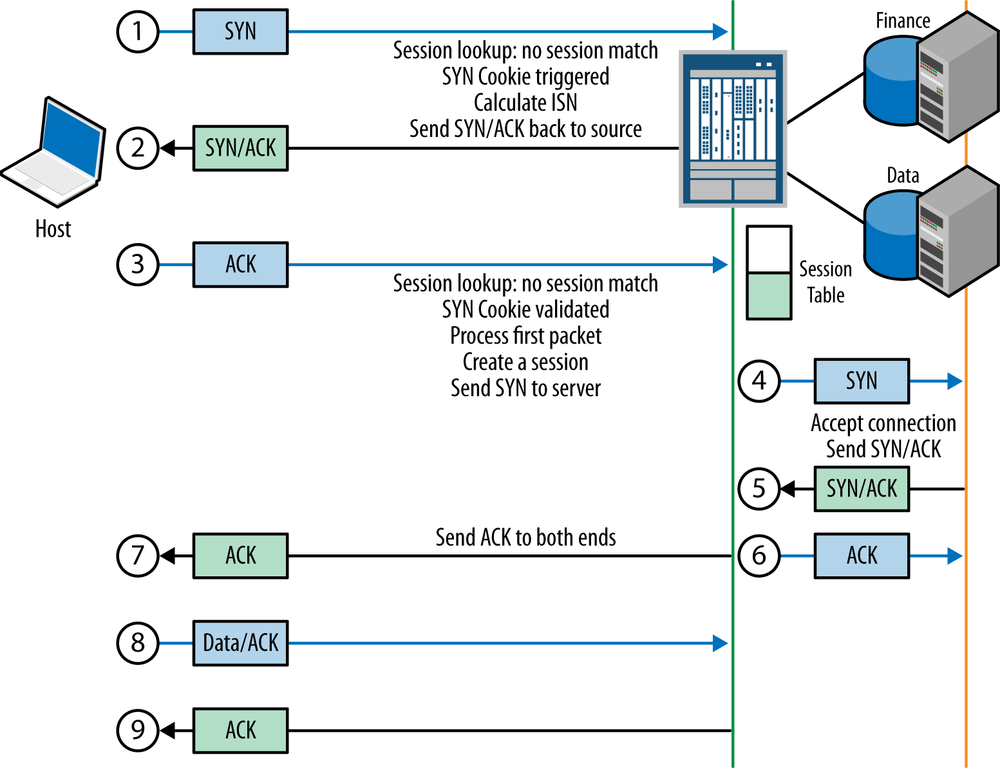
SYN Cookies (see Figure 11-5) work by responding to a client’s initial SYN with a SYN/ACK on behalf of the server. Instead of just setting a standard sequence number, the SRX will encode a sequence number based on a hash of the connection information tuple, plus a pseudorandom “magic” number known only to the SRX platform. At this point, the SRX won’t record any state of the connection, in case the SYN is spoofed. Instead, it will send the SYN/ACK back toward the client. If it was spoofed, the client will either drop the SYN or send a reset, but won’t process the packet. If the client is real, it will respond with its ACK using the sequence number provided by the server. If the sequence number doesn’t match what is expected, then the SRX will not process the connection. Essentially, this ensures that the client is real and not spoofed (assuming that the attacker isn’t in the same path) so that a host can’t do a massive spoofed SYN flood, and at the same time we can validate that the client is real. After the client has completed the three-way handshake, then the SRX will open the connection to the destination server. Of course, because the SRX uses a custom sequence number, it needs to rewrite the sequence numbers bidirectionally on the fly so that this operation is transparent to both the client and the server.
As for SYN Proxy, this feature also responds to the client’s SYN with a SYN/ACK and waits for the client to complete the handshake before establishing the TCP connection with the server. It will not start the connection until the handshake has completed.
The main difference between these two techniques is that SYN Cookie leverages the calculated sequence number in its SYN/ACK and doesn’t record any state until the three-way handshake is completed, whereas the SYN Proxy will not use a special TCP sequence number and will hold the state for the initial TCP timeout. Unless you have some special reason not to use SYN Cookie, it is recommended that you use it instead of SYN Proxy because it is lighter weight in the case of an attack.
There are three components of SYN Cookie/SYN Proxy that you should be aware of: the alarm threshold, the attack threshold, and the timeout. It functions as follows:
While the rate of incoming SYN packets for the Screen is below the alarm threshold, no action will be taken. Once it goes above the alarm threshold, a log will be generated indicating that the threshold has been reached, but no action will be taken.
When the SYNs go over the attack threshold, the SRX will go from normal TCP processing to implementing either SYN Cookie or SYN Proxy based on your configuration.
The SYN Cookie/SYN Proxy application will continue until the SYN rate has fallen below the attack threshold plus the timeout that you have defined.
If at any time the SYN packets go above the SYN source or destination flood threshold (tracked per host), the system will drop those packets. In a way this operates independently.
Optionally, in Junos 12.1 there is a whitelist object for SYN Flood Screen that can exempt hosts from SYN flood processing if you have certain needs for an individual server.
SYN Cookie/Proxy:
Screen Type: Per Packet
Screen Processing Location: CP/SPU for high-end SRX, Forwarding Engine branch SRX
Configuring SYN Cookie/Proxy Protection
In addition to the protection that you configured for SYN floods in the previous example, add SYN Cookie protection to your Screen with an alarm threshold of 1,000 SYNs per second, attack threshold of 1,500 SYNs per second, and a timeout of 30 seconds after the attack has subsided.
{primary:node0}[edit security screen]
root@SRX550-Node0# set ids-option Internet-Screen tcp syn-flood alarm-threshold 1000

{primary:node0}[edit security screen]
root@SRX550-Node0# set ids-option Internet-Screen tcp syn-flood attack-threshold 1500

{primary:node0}[edit security screen]
root@SRX550-Node0# set ids-option Internet-Screen tcp syn-flood timeout 30

{primary:node0}[edit security screen]
root@SRX550-Node0# top

{primary:node0}[edit]
root@SRX550-Node0# set security flow syn-flood-protection-mode syn-cookie

{primary:node0}[edit]
root@SRX550-Node0# show security screen
ids-option Internet-Screen {
    tcp {
        syn-flood {
            alarm-threshold 1000;
            attack-threshold 1500;
            source-threshold 100;
            destination-threshold 1000;
            timeout 30;
        }
    }
}

{primary:node0}[edit]
root@SRX550-Node0# show security flow
syn-flood-protection-mode syn-cookie;
SYN-Frag Screen
Another anomalous type of behavior with TCP is to fragment the packets so small that the TCP header can’t be fully viewed. In particular, this technique can be leveraged with SYN packets because it will cause the system to hold resources waiting for the other fragment, along with possibly preparing to set up the new connection. This can be leveraged to attack a firewall’s resources along with those of an end system. This behavior is highly suspicious and shouldn’t be seen legitimately in networks, so it should be blocked.
Screen Type: Per Packet
Screen Processing Location: NPU for high-end SRX, Forwarding Engine branch SRX
Configuring the SYN-Frag Screen
To configure the SYN-Frag Screen, it need only be enabled on the Screen profile. Remember that if you already block IP fragments with the Block IP Fragment Screen, this will supersede this Screen.
{primary:node0}[edit security screen]
root@SRX550-Node0# set ids-option Internet-Screen tcp syn-frag

{primary:node0}[edit security screen]
root@SRX550-Node0# show
ids-option Internet-Screen {
    tcp {
        syn-frag;
    }
}
TCP No Flags Screen
According to RFC 791, all TCP packets must have some flags set, as a TCP packet without flags set is invalid. Such packets should never be seen with legitimate traffic and likely signify that there is some malicious activity occurring, such as network scanning. Such packets should always be dropped.
Screen Type: Per Packet
Screen Processing Location: NPU for high-end SRX, Forwarding Engine branch SRX
Configuring the TCP No Flags Screen
Configuring the TCP No Flags Screen is quite simple as it is either on or off; there are no thresholds or other values that need to be configured.
{primary:node0}[edit security screen]
root@SRX550-Node0# set ids-option Internet-Screen tcp tcp-no-flag

{primary:node0}[edit security screen]
root@SRX550-Node0# show
ids-option Internet-Screen {
    tcp {
        tcp-no-flag;
    }
}
TCP Sweep Screen
Similar to the UDP and ICMP Sweep Screens, the TCP Sweep Screen is used to detect sweeps across different hosts on a network known as a horizontal scan (rather than a port scan, which is a vertical scan.) This behavior usually indicates a network reconnaissance scan being used to map your network, so typically this behavior should be blocked by the Screen to prevent an attacker from identifying important characteristics of your network.
Screen Type: Per Packet, Threshold
Screen Processing Location: CP/SPU for high-end SRX, Forwarding Engine branch SRX
Configuring the TCP Sweep Screen
For the TCP Sweep Screen, you need only configure the threshold of how many scan packets must be received before triggering the Screen. The threshold is how many microseconds to wait between seeing 10 scan packets. The lower the threshold, the faster this would kick in. In this example, we use 2,000 microseconds as our threshold, or 2 milliseconds.
{primary:node0}[edit security screen]
root@SRX550-Node0# set ids-option Internet-Screen tcp tcp-sweep threshold 2000

{primary:node0}[edit security screen]
root@SRX550-Node0# show
ids-option Internet-Screen {
    tcp {
        tcp-sweep threshold 2000;
    }
}
WinNuke Screen
WinNuke is a legacy Windows attack from the 1990s. With a single packet, this caused a Windows machine to blue screen. The TCP packet was sent to NetBIOS port 139 with the Urgent flag set, which resulted in the system instability. Although this attack is unlikely to impact modern OSs, it might still be worth enabling as it likely signifies malicious activity.
Screen Type: Per Packet
Screen Processing Location: NPU for high-end SRX, Forwarding Engine branch SRX
Note
More information about WinNuke is available at Wikipedia’s WinNuke entry.
Configuring the WinNuke Screen
The WinNuke Screen is simple to configure, as it is either on or off. You cannot configure the ports or flags for this Screen, nor their thresholds.
{primary:node0}[edit security screen]
root@SRX550-Node0# set ids-option Internet-Screen tcp winnuke

{primary:node0}[edit security screen]
root@SRX550-Node0# show
ids-option Internet-Screen {
    tcp {
        winnuke;
    }
}
Session Limit Screens
There are two session limit Screens at the time of writing this book: the Source-IP Session Limit and the Destination-IP Session Limit. Session limit Screens are important to consider deploying; without them, an attack could potentially create a DoS attack by consuming a large number of sessions so that the session table on the FW or on the end host is consumed, even if they are not sending a high volume of traffic. Such attacks have been seen with Slowloris and TCP SockStress. Although they are slightly different in nature, they both seek to consume sessions on the system by holding open connections.
Note
For more information on the Slowloris attack, see Wikipedia’s Slowloris entry.
For more information on TCP SockStress, an excellent write-up can be found at Wikipedia’s SockStress entry.
In other cases, misconfigured or compromised devices can also result in massive session consumption. All of these vectors could be mitigated by Session Limit Screens. Although they might not be the ultimate solution, they are very effective with using other Screens and settings to limit the impact of such session attacks.
Source IP Session Limit Screen
Limiting the number of sessions an individual source IP address can establish is a critically important control to limit different DoS attacks, particularly those that are not individual spoofed packets (which can be better handled with other components). To effectively configure this Screen, it is ideal to have a baseline of how many sessions you would expect an individual IP address to legitimately have. Because we can configure Screens with different profiles on a zone-by-zone basis, it is ideal to identify these limits based on the source of the traffic. For instance, an external resource accessing the DMZ web server likely has a different number of sessions than an internal user going out to the Internet.
There isn’t any perfect way to define how many sessions
an individual source should have, but an easy way is to enable this
Screen with the Alarm Without Drop Screen and start with a low number
and go up until you reach a level you think is legitimate and doesn’t
fire on normal activity—or you can start high and go lower. You can
also count sessions in the flow table to get an idea of how many
sessions per host. For instance, you could use show security flow session source-prefix
192.168.2.50/32 summary to get a count per host or per
subnet. Of course, not all hosts are going to be equal, but it gives
you a place to start.
When dealing with Screens on the Internet, you should also consider the fact that some hosts might be behind NAT devices, so be sure to give yourself a bit of extra room for this Screen.
Screen Type: Per Session
Screen Processing Location: CP/SPU for high-end SRX, Forwarding Engine branch SRX
Configuring the Source IP Session Limit Screen
Once you’ve identified the threshold that you want to configure, the Source IP Session Limit Screen is quite easy to implement: you merely define the value. In this example, we set a limit of 50 sessions per source IP address.
{primary:node0}[edit security screen]
root@SRX550-Node0# set ids-option Internet-Screen limit-session source-ip-based 50

{primary:node0}[edit security screen]
root@SRX550-Node0# show
ids-option Internet-Screen {
    limit-session {
        source-ip-based 50;
    }
}
Destination IP Session Limit Screen
The opposite of the Source IP Session Limit Screen is the Destination IP Session Limit Screen. Although not quite as powerful as the Source IP Session Limit Screen at limiting DoS attacks, this Screen is still effective, especially at protecting DMZ resources. For instance, you can use this Screen at the Internet-facing zone to limit how many sessions can go to your DMZ servers to prevent them from being overwhelmed by a session flood. Of course, this Screen should ideally be used in conjunction with the Source IP Session Limit Screen because it could result in a DoS for legitimate users if a source or group of sources can hit the destination limit. Additionally, this can be used to limit how many sessions internal users can access for individual external resources. This can be good to try to detect certain anomalous activity. Again, this Screen is best used in conjunction with the Source IP Limit Screen.
Screen Type: Per Session
Screen Processing Location: CP/SPU for high-end SRX, Forwarding Engine branch SRX
Configuring the Destination IP Session Limit Screen
The configuration for the Destination IP Session Limit Screen is identical to the configuration of the Source IP address. The same methods can be used to establish baselines for the Screen thresholds in your environment. For this example, we assume that we are protecting inbound sessions on a DMZ server farm that can handle up to 10,000 sessions per host.
{primary:node0}[edit security screen]
root@SRX550-Node0# set ids-option Internet-Screen limit-session destination-ip-based 10000

{primary:node0}[edit security screen]
root@SRX550-Node0# show
ids-option Internet-Screen {
    limit-session {
        destination-ip-based 10000;
    }
}
SRX Flow Options
The flow options on the SRX are often overlooked by administrators when setting up the SRX. Although they are a slightly more advanced topic, it is really important to understand them, particularly because their configuration can impact the function of the firewall. Juniper does try to set the default values to be as secure as possible, but it can cause issues in some environments, so it’s good to review these different options to ensure that they meet the needs of your network.
In this section, we do not cover all of the flow options, but instead cover those that are most pertinent to Screens, which include the Aging and TCP-Session Options. There are some ancillary flow options outside the scope of this chapter, including TCP MSS, IP Reassembly, and a few others, but the Aging and TCP-Session Screens can impact DoS attacks, which is the focus of this chapter.
Note
Unless otherwise specified, flow options are applied globally to the platform.
Aggressive session aging
A very commonly overlooked feature to prevent both intentional DoS attacks and outages caused by some other consumption of the session table is aggressive session aging. Essentially, this feature allows you to set a low and high threshold (watermark) for the platform session table consumption before it kicks into high gear and starts aggressively aging old idle sessions. In many deployments, due to complex application needs, administrators change the default timeouts of such applications from the system-defined defaults (30 minutes for TCP, 60 seconds for UDP and ICMP; IP protocols vary) to something much higher. For TCP, if the session is closed gracefully, we will end it immediately. For other protocols like UDP, IP, and ICMP, we can only close them using ALGs (e.g., for DNS); otherwise they will remain open until the session goes idle for the prescribed timeout. Under normal circumstances you might never approach the limits of your session table for your given platform—but this isn’t always the case, especially in a DoS attack or other misconfiguration.
Aggressive session aging is triggered when the percentage consumption of the session table goes above the high watermark. Then, instead of following the default idle timeout, the platform uses the new early-ageout timeout that is set for the flow. Of course, this only applies for sessions that are idle, not for sessions that are actively transmitting. You can think of it as an override of the default idle timeout when the high watermark condition is met. The aggressive session aging process will complete once the number of sessions goes below the low watermark you set. For instance, let’s say your platform supports 1 million firewall sessions and you set the high watermark as 80 percent and the low watermark as 60 percent, with an early ageout of three seconds. When the number of sessions goes above 800,000, the early ageout will kick in for any sessions that are idle for more than three seconds. This will continue until the session table dips below 600,000 sessions, when the normal session idle timeouts will resume (until you go back above 80 percent again).
At this point, you should also recognize the importance of leveraging the IP Session Limit Screens that we discussed in the last section, as they complement this feature very nicely by preventing an individual from consuming too many sessions.
Note
Aggressive session aging has been in the branch platforms since its inception in Junos 9.5, but was only recently added to the high-end SRX in Junos 11.4 and beyond.
Configuring the aggressive session ageout flow option
To configure aggressive session aging, you merely need
to determine your low and high watermarks as defined by percentage,
and the early ageout you would like to apply to sessions during the
aggressive session aging process. Because the values are applied as
a percentage, you don’t need to concern yourself with knowing the
exact session capacities of your platform, although you can always
determine it in the datasheets. It’s also important to note that
with new code optimizations and the shift to 64-bit or additional
memory, these limits might be further increased, so rather than post
them here, you should view the latest datasheets to make sure you
have an accurate understanding. You can also determine the max
session count and consumption for your platform with the show security monitoring fpc <x>
command if you have an SRX handy. Here we show this value for both
an SRX550 and an SRX3600.
root@SRX550-Node0> show security monitoring fpc 0
node0:
--------------------------------------------------------------------------
FPC 0
  PIC 0
    CPU utilization      :    7 %
    Memory utilization   :   67 %
    Current flow session :    23785 ←Current Session Consumption
    Max flow session     : 409600   ←Maximum Sessions (with IPv6 enabled)
Session Creation Per Second (for last 96 seconds on average):    0

root@srx3600n0> show security monitoring fpc 3
FPC 3
  PIC 0
    CPU utilization      :    5 %
    Memory utilization   :   70 %
    Current flow session : 127322    ←Current Utilizaiton for this SPU
    Max flow session     : 131072
    Current CP session   : 1477271 ←Currrent Utilization for this platform
    Max CP session       : 2359296 <-Max # of sessions per platform
Session Creation Per Second (for last 96 seconds on average): 6025
For this example, we configure the aggressive session aging Screen to activate at 80 percent and set an early ageout of three seconds. The session aging will terminate when the session utilization falls below 60 percent.
{primary:node0}[edit security flow]
root@SRX550-Node0# set aging high-watermark 80 low-watermark 60 early-ageout 3

{primary:node0}[edit security flow]
root@SRX550-Node0# show
aging {
    early-ageout 3;
    low-watermark 60;
    high-watermark 80;
}
TCP sequence checks
By default, the SRX enforces checks to ensure that packets arriving on the SRX for a session fall within the TCP window of the session. This prevents hijacking attacks against existing sessions by external attackers. The SRX monitors the TCP window as it progresses during the communication and ensures that TCP packets that arrive on the firewall fall within the window; otherwise they are dropped.
Note
A very detailed discussion of TCP and especially TCP windowing is available in TCP/IP by Craig Hunt (O’Reilly).
TCP sequence checks should normally be on for security purposes. Sometimes if the traffic is asymmetric (meaning that the SRX can only see one side of the flow), the TCP sequence check must be disabled.
Configuring TCP sequence checks
TCP sequence checks are enabled by default at the global platform level, or also on an FW rule-by-rule basis. If they are configured on a rule-by-rule basis, you must disable the TCP sequence check globally and then enable it per FW rule. Because they are enabled by default, the only global configuration option is to disable them (see Examples 11-1 and 11-2).
{primary:node0}[edit security flow]
root@SRX550-Node0# set tcp-session no-sequence-check

{primary:node0}[edit security flow]
root@SRX550-Node0# show
tcp-session {
    no-sequence-check;
}{primary:node0}[edit security flow]
root@SRX550-Node0# set tcp-session no-sequence-check
{primary:node0}[edit security flow]
root@SRX550-Node0# show
tcp-session {
no-sequence-check;
}
root@SRX550-Node0# set security policies from-zone trust to-zone untrust policy 1 match source-address any destination-address any application any
{primary:node0}[edit]
root@SRX550-Node0# set security policies from-zone trust to-zone untrust policy 1 then permit tcp-options sequence-check-required
{primary:node0}[edit]
root@SRX550-Node0# set security policies from-zone trust to-zone untrust policy 1 then log session-close
{primary:node0}[edit]
root@SRX550-Node0# show security policies
from-zone trust to-zone untrust {
policy 1 {
match {
source-address any;
destination-address any;
application any;
}
then {
permit {
tcp-options {
sequence-check-required;
}
}
log {
session-close;
}
}
}
}In this example, we disabled the TCP sequence check globally and enabled the TCP sequence check per FW rule.
Configuring TCP sequence checks for RST packets
To prevent an attacker from sending a TCP reset flood with the desire to close sessions, you can also enforce the checking of the TCP Reset packets to ensure that they are in sequence as well.
{primary:node0}[edit security flow]
root@SRX550-Node0# set tcp-session rst-sequence-check

{primary:node0}[edit security flow]
root@SRX550-Node0# show
tcp-session {
    rst-sequence-check;
}
TCP SYN checks
By default, the SRX will check any new inbound TCP session to ensure that it is statefully established with a SYN first by the client. In some cases, you might need to disable the SYN checking because of asymmetric traffic flows. Asymmetric traffic through a firewall greatly reduces its effectiveness (particularly with Layer 7 security) and is not advisable. If you must disable SYN checks, that can either be done globally or enabled on a per FW rule basis as shown here.
{primary:node0}[edit security flow]
root@SRX550-Node0# set tcp-session no-syn-check

{primary:node0}[edit security flow]
root@SRX550-Node0# show
tcp-session {
    no-syn-check;
}

root@SRX550-Node0# set security policies from-zone trust to-zone untrust policy 1 match source-address any destination-address any application any

{primary:node0}[edit]
root@SRX550-Node0# set security policies from-zone trust to-zone untrust policy 1 then permit tcp-options syn-check-required

{primary:node0}[edit]
root@SRX550-Node0# set security policies from-zone trust to-zone untrust policy 1 then log session-close


{primary:node0}[edit]
root@SRX550-Node0# show security policies
from-zone trust to-zone untrust {
    policy 1 {
        match {
            source-address any;
            destination-address any;
            application any;
        }
        then {
            permit {
                tcp-options {
                    syn-check-required;
                }
            }
            log {
                session-close;
            }
        }
    }
}
Strict SYN checks
By default, the SYN check only ensures that the first packet sent from client to server is a SYN packet. However, you can ensure that the handshake is a true three-way handshake with the client sending the SYN, the server responding with the SYN/ACK, and then the client responding with an ACK using the strict SYN check. This can be used to ensure that no other anomalous negotiation takes place, including the TCP split handshake, where the client sends a SYN, followed by the server sending a SYN back to the client, the client sending the SYN/ACK, and the server sending the SYN. This is part of the TCP RFC 791 that most people don’t know. Although it isn’t an issue for the SRX firewall (we don’t mistake which direction the flow is going and who is the client and server), it can be for other firewalls, and especially for Layer 7 devices that might get this confused (UTM, IPS, load balancers, etc.). Again, this is not a problem for Juniper equipment, but it usually a good idea to enable it.
SYN checks in tunnels
The SRX supports disabling TCP SYN checks for tunneled traffic separate from the global clear-text values. This can be useful when you have asymmetric routing with IPsec tunnels or for IPsec session failover. Although it isn’t ideal to disable the SYN checks for tunneled traffic, a tunnel is not quite as unsolicited as normal traffic can be from the Internet, so there is a bit more confidence in the traffic arriving.
{primary:node0}[edit security flow]
root@SRX550-Node0# set tcp-session no-syn-check-in-tunnel

{primary:node0}[edit security flow]
root@SRX550-Node0# show
tcp-session {
    no-syn-check-in-tunnel;
}
TCP state timeouts
Besides the standard application timeouts that can be configured on an application-by-application basis, you can also apply a special timeout for TCP sessions in the initial state and time wait states.
The TCP initial timeout is the timeout that is imposed after the SYN has been seen but before the session is fully established. This is to prevent a full TCP session with a default of 30 minutes from being established on the firewall without the client/server fully establishing the session. By default, the value is 20 seconds at the time of writing this book.
Note
This does not apply if SYN checking is disabled, in which case the session will be established immediately.
The TCP wait state timeout is used to keep a session in memory in the “CLOSED” state after it has been terminated by a FIN/RESET. The purpose of this is to ensure that old delayed packets that might be received after the session has been closed can be properly handled and won’t end up as part of a new TCP session. You have two options: you can either use the default two-second timeout, or you can instruct the firewall to use the default ageout for that application. We recommend just using the default option unless you have an explicit need to change it.
Configuring the TCP initial session timeout and TCP time wait timeout
In this example, we configure the TCP initial session timeout for a value of 25 seconds, and the TCP time wait timeout will be 3 seconds.
{primary:node0}[edit security flow]
root@SRX550-Node0# set tcp-session time-wait-state session-timeout 3

{primary:node0}[edit security flow]
root@SRX550-Node0# set tcp-session tcp-initial-timeout 25

{primary:node0}[edit security flow]
root@SRX550-Node0# show
tcp-session {
    tcp-initial-timeout 25;
    time-wait-state {
        session-timeout 3;
    }
}
Best Practices
With so many options discussed in this chapter, it is easy to get lost when it comes to what you should actually configure in real deployments. Here’s a bit of guidance when looking at deploying Screens and flow options.
First, gain an understanding of the firewall and the segments to which it connects. You need to have an understanding of traffic volumes and expected behaviors in the network.
Remember that you can always initially deploy Screens with the Alarm Without Drop Setting per Screen Profile. This allows you to test the waters so to speak when it comes to deploying Screens to ensure that your thresholds are properly set, and that some of the packet anomaly signatures are not firing on broken applications.
If you do not have an idea of what your thresholds are, you can examine various output commands on the SRX, along with using a sliding scale for the Screen threshold configuration to determine what thresholds you want to set.
Don’t forget to enable Screens on network segments that you control, not just the Internet segments. You will likely want to use a separate Screen profile for different segments as the acceptable threshold limits and anomaly Screens might be different. Additionally, you might want to enable alarm without drop on internal segments if you don’t want the Screens to be enforced, although it is best to turn this off once you have a handle on the configuration.
It is a very good idea to set up both flood-based Screens and session limit Screens, particularly on the Internet-facing segments or segments that your organizations don’t control. Some of the packet anomalies might be harmless to modern OSs, but the flood-based attacks are perpetual and not only affect the end systems, but can impact the firewalls as well.
Just like standard firewall policy rules, you should leverage the concept of least privilege with Screens as well. This means that if it isn’t explicitly needed on the network for accepted behavior, it should be denied by Screens.
Don’t forget to examine the flow options that can be configured to assist in preventing certain DoS attacks and other network outages.
Although we didn’t cover stateless filters and ingress policers in this chapter, they can also complement Screens, along with a solid firewall policy, IPS, and AppDDoS protection.
Finally, if at all possible, you should always leave SYN checking and TCP sequence checking on. Although it might not always be possible due to network architecture, disabling these features can expose end systems to potential TCP attack vectors. If you must disable them, you might want to consider using per FW rule SYN/SEQ checks to provide some point security.
Troubleshooting and Operation
Operating Screens can be greatly simplified by keeping a few resources in mind. In this section, we examine a few Screen and flow options that will aid in the operation of the features.
Viewing Screen Profile Settings
You can easily view the configuration of a Screen profile
from the configuration mode using the show
security screen ids-option <Screen> command.
{primary:node0}
root@SRX100HM> show security screen ids-option Screen
node0:
-----------------------------------------------------------------
Screen object status:

Name                                         Value
  ICMP flood threshold                       200
  UDP flood threshold                        1000
  TCP winnuke                                enabled
  TCP port scan threshold                    1000
  ICMP address sweep threshold               2000
  TCP sweep threshold                        1000
  UDP sweep threshold                        1000
  IP tear drop                               enabled
  TCP SYN flood attack threshold             100
  TCP SYN flood alarm threshold              50
  TCP SYN flood source threshold             100
  TCP SYN flood destination threshold        100
  TCP SYN flood timeout                      30
  IP spoofing                                enabled
  ICMP ping of death                         enabled
  IP source route option                     enabled
  TCP land attack                            enabled
  TCP SYN fragment                           enabled
  TCP no flag                                enabled
  IP unknown protocol                        enabled
  IP bad options                             enabled
  IP record route option                     enabled
  IP timestamp option                        enabled
  IP security option                         enabled
  IP loose source route option               enabled
  IP strict source route option              enabled
  IP stream option                           enabled
  ICMP fragmentation                         enabled
  ICMP large packet                          enabled
  TCP SYN FIN                                enabled
  TCP FIN no ACK                             enabled
  Session source limit threshold             500
  Session destination limit threshold        500
  Alarm without drop                         enabled
Viewing the Screen Attack Statistics
During operation, you might want to get information on how
often the Screens are firing on the platform. You can do this by viewing
the output of the show security screen
statistics interface|zone <interface|zone> command,
which is either per interface or per zone.
{primary:node0}
root@SRX100HM> show security screen statistics zone untrust
node0:
----------------------------------------------------------------
Screen statistics:

IDS attack type                              Statistics
  ICMP flood                                 255
  UDP flood                                  10241
  TCP winnuke                                0
  TCP port scan                              0
  ICMP address sweep                         73
  TCP sweep                                  0
  UDP sweep                                  0
  IP tear drop                               0
  TCP SYN flood                              0
  IP spoofing                                8991
  ICMP ping of death                         0
  IP source route option                     0
  TCP land attack                            0
  TCP SYN fragment                           0
  TCP no flag                                431
  IP unknown protocol                        28
  IP bad options                             0
  IP record route option                     0
  IP timestamp option                        0
  IP security option                         0
  IP loose source route option               0
  IP strict source route option              0
  IP stream option                           0
  ICMP fragment                              0
  ICMP large packet                          0
  TCP SYN FIN                                0
  TCP FIN no ACK                             0
  Source session limit                       5432
  TCP SYN-ACK-ACK proxy                      0
  IP block fragment                          0
  Destination session limit                  15
Viewing Flow Exceptions
In addition to the various Screen stats that you might be interested in viewing, there are numerous options per interface that might be of interest. As you can see next, the output of the interface stats includes not only information about bytes and packets transmitted and QoS information, but also a great deal of very valuable flow exception information. These counters can be indicative of suspicious activity on the network as well.
{primary:node0}
root@SRX100HM> show interfaces reth0 extensive
Physical interface: reth0, Enabled, Physical link is Up
  Interface index: 128, SNMP ifIndex: 527, Generation: 157
  Link-level type: Ethernet, MTU: 1514, Speed: 100mbps, BPDU Error: None, MAC-REWRITE Error: None, Loopback: Disabled, Source filtering: Disabled, Flow control: Disabled,
  Minimum links needed: 1, Minimum bandwidth needed: 0
  Device flags   : Present Running
  Interface flags: SNMP-Traps Internal: 0x0
  Current address: 00:10:db:ff:20:10, Hardware address: 00:10:db:ff:20:10
  Last flapped   : 2012-08-16 14:19:04 EDT (1w1d 21:07 ago)
  Statistics last cleared: Never
  Traffic statistics:
   Input  bytes  :          13475873486                10512 bps
   Output bytes  :          25926029274                 9608 bps
   Input  packets:             22960010                    9 pps
   Output packets:             33791779                    9 pps
  Dropped traffic statistics due to STP State:
   Input  bytes  :                    0
   Output bytes  :                    0
   Input  packets:                    0
   Output packets:                    0
  Input errors:
    Errors: 0, Drops: 0, Framing errors: 0, Runts: 0, Giants: 0, Policed discards: 0, Resource errors: 0
  Output errors:
    Carrier transitions: 0, Errors: 0, Drops: 0, MTU errors: 0, Resource errors: 0
  Ingress queues: 8 supported, 4 in use
  Queue counters:       Queued packets  Transmitted packets  Dropped packets
    0 best-effort                    0                    0                0
    1 expedited-fo                   0                    0                0
    2 assured-forw                   0                    0                0
    3 network-cont                   0                    0                0
  Egress queues: 8 supported, 4 in use
  Queue counters:       Queued packets  Transmitted packets  Dropped packets
    0 best-effort             33840462             33840462                0
    1 expedited-fo                   0                    0                0
    2 assured-forw                   0                    0                0
    3 network-cont                 307                  307                0
  Queue number:         Mapped forwarding classes
    0                   best-effort
    1                   expedited-forwarding
    2                   assured-forwarding
    3                   network-control

  Logical interface reth0.0 (Index 70) (SNMP ifIndex 531) (Generation 156)
    Flags: SNMP-Traps 0x0 Encapsulation: ENET2
    Statistics        Packets        pps         Bytes          bps
    Bundle:
        Input :      22960010          9   13475873486        10512
        Output:      33791779          9   25902216474         9608
    Link:
      fe-1/0/1.0
        Input :           169          0         24604            0
        Output:             0          0             0            0
      fe-0/0/1.0
        Input :      22959841          9   13475848882        10512
        Output:      33791779          9   25902216474         9608
    Marker Statistics:   Marker Rx  Resp Tx   Unknown Rx   Illegal Rx
      fe-1/0/1.0                 0        0            0            0
      fe-0/0/1.0                 0        0            0            0
    Security: Zone: Untrust
    Allowed host-inbound traffic : ike ping
    Flow Statistics :
    Flow Input statistics :
      Self packets :                     384590
      ICMP packets :                     258667
      VPN packets :                      4221134
      Multicast packets :                0
      Bytes permitted by policy :        11951135993
      Connections established :          26276
    Flow Output statistics:
      Multicast packets :                0
      Bytes permitted by policy :        24882784274
    Flow error statistics (Packets dropped due to):
      Address spoofing:                  0
      Authentication failed:             0
      Incoming NAT errors:               0
      Invalid zone received packet:      0
      Multiple user authentications:     0
      Multiple incoming NAT:             0
      No parent for a gate:              0
      No one interested in self packets: 135
      No minor session:                  0
      No more sessions:                  0
      No NAT gate:                       0
      No route present:                  46566
      No SA for incoming SPI:            2890
      No tunnel found:                   0
      No session for a gate:             0
      No zone or NULL zone binding       0
      Policy denied:                     37
      Security association not active:   1440
      TCP sequence number out of window: 3
      Syn-attack protection:             0
      User authentication errors:        0
    Protocol inet, MTU: 1500, Generation: 180, Route table: 4
      Flags: Sendbcast-pkt-to-re, Is-Primary
      Input Filters: Inbound-QoS
      Addresses, Flags: Is-Default Is-Preferred Is-Primary
        Destination: 192.168.1.1/24, Local: 192.168.1.1, Broadcast: 192.168.1.1, Generation: 170
Sample Deployment
For this sample deployment, we configure two Screen profiles that will be applied on our SRX5800 Internet edge firewalls. The first Screen profile will be called Internet-Screen and will be applied to the Internet zone, and the second Screen profile will be called Internal-Screen and will be applied to the LAN (Dept-A, Dept-B, and Internal-Servers) and DMZ zones. The goal is to ensure that we have a solid Screen profile to protect internal resources from inbound Internet attacks, while also flagging (but not disrupting) any suspicious internal activity for further investigation. The profiles will be set up as follows:
- Internet-Screen
Enforce all actions with packet drops.
Deny all packet-based anomalies for TCP, UDP, IP, and ICMP, but allow for IP fragments.
Limit individual source IPs on the Internet to only 100 sessions per host, and only allow each DMZ server to accept 25,000 sessions. There is no policy to allow inbound traffic directly from the Internet to the internal network so this Screen won’t impact the internal zone.
To prevent scanning, ensure that the minimum value is set between IP, TCP, UDP, and TCP port scan sweeps.
To prevent flooding, only allow each host to send 100 SYNs per second, and receive no more than 1,000 SYNs, 1,000 UDP, and 300 ICMP packets per second.
Set a timeout of 30 seconds on the SYN attacks, with an alarm threshold of 750 SYNs per second, and when SYN packets hit 2,000 per second initiate SYN Cookies.
- Internal-Screens (Dept-A, Dept-B, Internal Servers Zones)
Log all violations but no packet drops.
Look for all packet-based anomalies except IP fragmentation.
Internal sources with more than 300 sessions should be flagged.
Look for suspicious port scan activity by setting a violation for more than 10 packets per 5,000 microseconds for TCP, UDP, and IP/ICMP.
Any host that sends more than 200 SYNs per second, 2,000 UDP packets, or 100 ICMP packets should be flagged.
- Flow Options
Ensure strict SYN checks are enabled.
If the session table goes above 80 percent utilization, initiate an early ageout of two seconds until the platform goes below 65 percent.
Configuration for Screen and Flow Option Sample Deployment
This configuration would look as follows:
root@SRX5800> show configuration security screen
ids-option Internet-Screen {
    icmp {
        ip-sweep threshold 1000;
        fragment;
        large;
        flood threshold 300;
        ping-death;
    }
    ip {
        bad-option;
        record-route-option;
        timestamp-option;
        security-option;
        stream-option;
        spoofing;
        source-route-option;
        loose-source-route-option;
        strict-source-route-option;
        unknown-protocol;
        tear-drop;
    }
    tcp {
        syn-fin;
        fin-no-ack;
        tcp-no-flag;
        syn-frag;
        port-scan threshold 1000;
        syn-flood {
            alarm-threshold 750;
            attack-threshold 2000;
            source-threshold 50;
            destination-threshold 1000;
            timeout 30;
        }
        land;
        winnuke;
        tcp-sweep threshold 1000;
    }
    udp {
        flood threshold 1000;
        udp-sweep threshold 1000;
    }
    limit-session {
        source-ip-based 100;
        destination-ip-based 25000;
    }
}


ids-option Internal-Screen {
    alarm-without-drop;
    icmp {
        ip-sweep threshold 5000;
        fragment;
        large;
        flood threshold 100;
        ping-death;
    }
    ip {
        bad-option;
        record-route-option;
        timestamp-option;
        security-option;
        stream-option;
        spoofing;
        source-route-option;
        loose-source-route-option;
        strict-source-route-option;
        unknown-protocol;
        tear-drop;
    }
    tcp {
        syn-fin;
        fin-no-ack;
        tcp-no-flag;
        syn-frag;
        port-scan threshold 5000;
        syn-flood {
            source-threshold 200;
        }
        land;
        winnuke;
        tcp-sweep threshold 5000;
    }
    udp {
        flood threshold 2000;
        udp-sweep threshold 5000;
    }
    limit-session {
        source-ip-based 300;
    }
}

root@SRX5800> show configuration security flow
syn-flood-protection-mode syn-cookie;
aging {
    early-ageout 2;
    low-watermark 66;
    high-watermark 80;
}
tcp-session {
    strict-syn-check;
}

root@SRX5800> show configuration security zones
security-zone Internet {
    screen Internet-Screen;
    interfaces {
        reth0.0 {
}
security-zone Dept-A {
    screen Internal-Screen;
    interfaces {
        reth1.0 {
}
security-zone Dept-B {
    screen Internal-Screen;
    interfaces {
        reth1.1 {
}
security-zone Internal-Servers {
    screen Internal-Screen;
    interfaces {
        reth1.2 {
}

security-zone DMZ {
    screen Internal-Screen;
    interfaces {
        reth2.0 {
}
Summary
The importance of deploying Screens cannot be overstated in modern networks. Most administrators might think that Level 3 and Level 4 attacks are ancient history, but many of them are perpetual and are just as effective today as they were at their inception—there’s just better protection against these attacks today. Screens and flow options are the missing piece to this puzzle that is often overlooked in deployments. In this chapter, we not only explored how they function, but also how the attacks they prevent against work, and how they can be leveraged to protect both your end systems and the SRX itself. With this information, you can ensure that you are adequately protected against such attacks so you can focus your efforts on the much more challenging ones such as those at Layer 7.
Study Questions
- Questions
At what OSI layers do the SRX Screens function?
How are Screens applied to the SRX?
What option is available to only log the Screen attack detection?
What are the two types of Screens that the SRX leverages?
What flow option is available to change the idle timeout of sessions when the firewall’s session table becomes heavily utilized?
What’s the difference between SYN checks and strict SYN checks?
What are the two methods that the SRX can use to validate that SYN packets are not spoofed?
Where can TCP sequence and SYN checks be configured?
What type of RPF check does the IP Spoofing Screen use?
How does the SRX perform a TCP sequence check?
Where are Screens processed in the packet flow? On the ingress side (arriving on the SRX) or on the egress side (leaving the SRX)?
If traffic arrives on the Internet zone destined for the DMZ, and you want to apply a Screen to protect the DMZ, would you apply it to the Internet zone or the DMZ?
- Answers
Layers 3 and 4 of the OSI model.
Screens are configured as profiles that can be applied at the zone level on a zone-by-zone basis.
The Alarm Without Drop action is available per Screen profile and can be used only to log when an attack is detected with Screens rather than to enforce the blocking.
The SRX has both flood- and anomaly-based Screens. The flood Screens leverage a threshold, whereas the anomaly Screens are processed per packet.
The aggressive session aging feature can be used to set a new ageout timeout when the high session watermark is surpassed.
SYN checks only check that the first packet in the session is a SYN (no other flags) packet, whereas the strict SYN check enforces that the client sends a SYN, followed by the SYN/ACK from the server and the ACK from the client.
SYN Cookies and SYN Proxy can be used to validate that the sender is not spoofing the SYN packet by establishing the session on the firewall first before doing so on the end system.
TCP SYN and SEQ checks can be configured both at the global level and on a per FW rule basis.
The IP Spoofing Screen uses a Loose Reverse Path Forwarding lookup to determine IP spoofing.
The SRX checks to ensure that the TCP packet’s sequence number is within the current TCP window range of the flow. If it is not, it will drop the packet.
Screens are processed on the ingress side when packets arrive, regardless of which side is the client or server.
You would place this on the Internet side. If you applied it to the DMZ side, it would only be applied when packets are sent from the DMZ to the Internet.
Get Juniper SRX Series now with the O’Reilly learning platform.
O’Reilly members experience books, live events, courses curated by job role, and more from O’Reilly and nearly 200 top publishers.

