Chapter 7. Sprites and Text
Even though OpenGL ES is designed for 3D graphics, you’ll often find the need to render visual elements that are 2D. OpenGL is actually quite well-suited to rendering a flat world; several popular 2D libraries, such as cocos2d, use OpenGL as their rendering engines.
The most common type of 2D rendering is text rendering. The OpenGL API lives too close to the metal to treat text as a first-class citizen, but it’s easy to render a pregenerated glyph (a character’s shape in a given font) using a textured quad, and that’s the approach we’ll take in this chapter.
Note
Computing the points along the outline of a
glyph can be surprisingly complex. For example, the TrueType file format
specifies a unique programming language—complete with loops and
if statements—solely for the purpose of tweaking the
curves in a glyph.
In this chapter, we won’t attempt to go over kerning algorithms, ligatures, or line wrapping; simple text layout is good enough for our purposes. (Check out the popular pango library if you need a full-featured layout engine.)
Another common 2D concept is the sprite, which is a rather generic term for any bitmap that gets composited into a scene. Sprites often contain transparent regions, so their texture format contains alpha. Sprites are often animated in some way. There are two ways of animating a sprite: its screen position can change (imagine a bouncing ball), or its source image can change (imagine a ball that’s spinning in place).
The iPhone supports two extensions to OpenGL ES
1.1 that make it easy to render sprites:
GL_OES_draw_texture and
GL_OES_point_sprite. We’ll make good use of both these
extensions throughout the chapter, and we’ll wrap up the chapter with a fun
sample application that renders a spring system with sprites.
Text Rendering 101: Drawing an FPS Counter
Rather than demonstrating text rendering with yet another goofy toy application, let’s do something useful for a change. Overlaying a frames-per-second counter in one corner of the iPhone screen provides a quick and easy way of evaluating graphics performance; see Figure 7-1.

Note
For more sophisticated runtime analysis of graphics performance, Apple provides an excellent free tool called Instruments, which we’ll cover in a subsequent chapter.
Before writing any application code, you’d need to generate an image that contains bitmaps for the numbers zero through nine, as depicted in Figure 7-2. (Don’t bother trying to create this yet; you’ll see a way to automate this shortly.)
You probably already guessed that you need to store off the bounding box of each glyph in order to compute the appropriate texture coordinates. Thinking about this a bit more, you’ll realize a mere bounding box is not enough. When you’re writing a sentence on ruled paper, some parts of letters extend below the baseline, like the descender of the lowercase p. And, in the case of the rather artsy font shown in Figure 7-3, the type designer wants the 9 numeral to be vertically offset from the other letters. Further complicating matters is the fact that the bounding boxes of glyphs can overlap in the destination image. In Figure 7-3, observe how the descender of the letter p extends right below the letter i.

It turns out that associating a specific set of glyph metrics with each character supplies enough information to achieve the simple text layout shown in Figure 7-3. A popular naming convention for these metrics is described in Figure 7-4; in this diagram, the origin represents the current pen position.
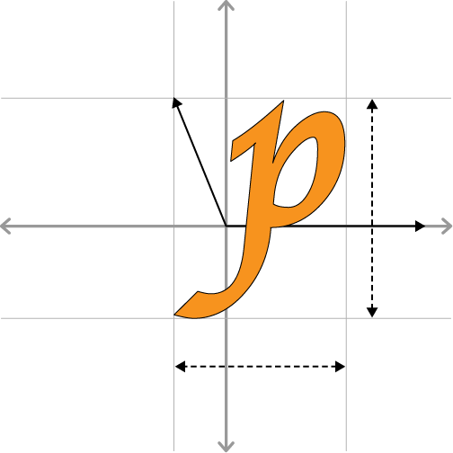
To summarize, the four glyph metrics are as follows:
Using these metrics, Example 7-1 the pseudocode for a simple text layout algorithm.
Generating a Glyphs Texture with Python
Before writing any application code, we need to choose a way of generating a glyphs texture and a set of metrics for each glyph.
Leveraging Quartz is perhaps the most obvious way of generating a glyphs texture (see Generating and Transforming OpenGL Textures with Quartz). This can be done at runtime when your application first starts up. This might slow down your startup time by a tiny amount, but it has the benefit of shrinking the size of the application bundle.
My preference is to generate the glyphs texture as a build step, mostly because it simplifies my application code. Build steps take place in Xcode rather than the iPhone execution environment, which brings a much richer tool set to the table. This is a perfect use case for a scripting language, and Python comes to mind first.
Note
There are many ways of generating a glyphs texture; here I’m giving an overview of my favorite. Take it only as a high-level example.
Given that we’re using Python in a build step, we need to find some useful Python modules for image manipulation and image generation. At the time of this writing, the Python Imaging Library (PIL) is the most popular imaging manipulation module, and it provides excellent support for manipulating PNG images at a low level. However, it’s not quite enough on its own because it doesn’t provide direct access to the glyph metrics that we need. Another popular library is Cairo, which has a well-maintained Python binding called pycairo. Cairo is robust and fast, and it’s used as the rendering backend in Firefox, Mono, and GTK. So, let’s go with PIL (http://www.pythonware.com/products/pil/) and pycairo (http://www.cairographics.org/pycairo/).
Rather than packaging the glyphs texture as a
PNG or PVR file, let’s serialize the data to a C header file. Since it’s
a single-channel texture, the amount of data is relatively small. The
header file will also provide a convenient place to store the glyph
metrics. We’ll simply have our Python script spawn
PVRTexTool (see the section entitled The PowerVR SDK and Low-Precision Textures) for generating the header file from the
image. We’ll still generate a PNG file for preview purposes, but we
won’t include it in the application bundle. See Example 7-2 for the complete Python script that
generates Figure 7-2.
import cairo import os from PIL import Image # Create a Cairo image surface: imagesize = (256,32) surface = cairo.ImageSurface(cairo.FORMAT_ARGB32, *imagesize)cr = cairo.Context(surface) padding = 3 # Choose a font (look in /Library/Fonts) and set up the transforms. cr.select_font_face("Apple Chancery", cairo.FONT_SLANT_NORMAL, cairo.FONT_WEIGHT_BOLD)
cr.set_font_size(32) cr.set_source_rgb(1,1,1)
# Create a string for appending the glyph metrics to the texture file: glyphs = '''
struct GlyphPosition { int X; int Y; };\n struct GlyphMetrics { int XBearing; int YBearing; int Width; int Height; int XAdvance; int YAdvance; };\n struct Glyph { GlyphPosition Position; GlyphMetrics Metrics; };\n static const Glyph NumeralGlyphs[] = {\n''' # Render glyphs '0' through '9' and write out their extents: x, y = 0, 0
for character in '0123456789':
extents = cr.text_extents(character)
x_bearing, y_bearing, width, height, x_advance, y_advance = extents glyphs += ' {{ %d, %d }, ' % (x, y)
glyphs += '{ %d, %d, %d, %d, %d, %d }},\n' % extents
cr.save() cr.translate(x, -y_bearing) cr.text_path(character) cr.fill()
cr.restore() x += width + padding
glyphs += '};\n' # Extract the alpha channel and open it up for a quick preview: surface.write_to_png("NumeralsTexture.png")
image = Image.open("NumeralsTexture.png")
image.load() image.split()[3].save("NumeralsTexture.png")
os.system("open NumeralsTexture.png") # Serialize the image data to a C header file: os.system('PVRTexTool -h -yflip1 -fOGL8 -iNumeralsTexture.png')
# Write to the header file: headerFile = open('NumeralsTexture.h', 'a') (16) headerFile.write(glyphs) headerFile.close()
Note
For this to work, you must either put the
location of PVRTexTool (The PowerVR SDK and Low-Precision Textures) into your shell’s PATH environment
variable or copy PVRTexTool into one of your PATH
entries, such as /usr/local/bin. If you’ve
extracted the Khronos SDK into your current directory, you could copy
the file and mark it executable with these commands:
cd SDKPackage/Utilities/PVRTexTool/PVRTexToolCL/MacOS
sudo cp PVRTexTool /usr/local/bin
sudo chmod +x /usr/local/bin/PVRTexTool
cd -
Cairo is a fairly extensive library and is beyond the scope of this book, but here’s a brief explanation of Example 7-2:
-
Create a 256×32 image surface with Cairo, and then create a context associated with the surface.
-
Select a TrueType font file, and then choose its size. In this case, I’m selecting the Apple Chancery font found in /Library/Fonts.
-
-
Initialize a string that we’ll later append to the header file. For starters, define some structs for the glyphs table.
-
-
-
-
Populate the
GlyphPositionstructure that we’re defining in the generated header file.-
Populate the
GlyphMetricsstructure that we’re defining in the generated header file.-
-
-
-
-
Use PIL to extract only the alpha channel, and then overwrite the PNG file.
-
Use
PVRTexToolto serialize the image data to a C header file. (At this point, the PNG is no longer needed.)- (16)
Append the metrics data to the same header file that defines the image data.
If you’d like, you can add the number-generation script to your Xcode project and make it into a build step, similar to what we did for texture compression (Texture Compression with PVRTC). For simplicity’s sake, I chose not to do this in the sample project that you can download from this book’s website.
Rendering the FPS Text
Now that we’re past the grunt work of generating the glyphs texture, we can move on to the actual rendering code. A frames-per-second counter is much more useful than our other toy demos, so this time let’s strive to make the rendering code very self-contained and easy to integrate into any project. We can do this by creating a C++ class wholly implemented within a single header file. Example 7-3 shows the basic outline for this class.
#include <OpenGLES/ES1/gl.h>
#include <OpenGLES/ES1/glext.h>
#include <mach/mach.h>
#include <mach/mach_time.h>
#include "../Textures/NumeralsTexture.h"

typedef unsigned int PVRTuint32;

struct PVR_Texture_Header {
    // ...see PVRTTexture.h in the PowerVR SDK...
};

class FpsRenderer {
public:
    FpsRenderer(vec2 windowSize)
    {
        ...
    }
    void RenderFps()
    {
        ...
    }

private:

    static const int MaxNumDigits = 3;
    static const int VertsPerDigit = 6;
    static const int FloatsPerVert = 4;
    static const int FloatsPerDigit = VertsPerDigit * FloatsPerVert;
    static const int TexCoordOffset = sizeof(float) * 2;
    static const int BytesPerVert = sizeof(float) * FloatsPerVert;
    static const int BytesPerDigit = sizeof(float) * FloatsPerDigit;

    uint64_t GetElapsedNanoseconds()
    {
        uint64_t current = mach_absolute_time();
        uint64_t duration = current - m_previousTime;
        m_previousTime = current;
        mach_timebase_info_data_t info;
        mach_timebase_info(&info);
        duration *= info.numer;
        duration /= info.denom;
        return duration;
    }

    float* WriteGlyphVertex(const Glyph& glyph, vec2 pos, int corner, float* vertex)
    {
        ...
    }

    double m_filterConstant;
    double m_fps;
    uint64_t m_previousTime;
    vec2 m_windowSize;
    vec2 m_textureSize;
    GLuint m_textureHandle;
    GLuint m_vbo;
};
-
Private method that generates the vertex and texture coordinates for one of the corners in a glyph rectangle.
-
Smoothing factor for the low-pass filter; this is explained further in the next section.
-
Exponentially weighted moving average of the frame rate (again, this is explained in the next section).
-
Timestamp in nanoseconds of the most recent call to
RenderFps().-
-
-
-
The OpenGL ID of the vertex buffer object used for rendering the glyphs.
Stabilizing the counter with a low-pass filter
To prevent the FPS counter from fluctuating wildly, we’ll using a low-pass filter similar to the one we used for the accelerometer (see Adding accelerometer support). The application can compute a constant called the smoothing factor, which is always between zero and one. Here’s one way of doing so:
double ComputeSmoothingFactor(double sampleRate, double cutoffFrequency)
{
   double dt = 1.0 / sampleRate;
   double RC = 1.0 / cutoffFrequency;
   return dt / (dt + RC);
}
In the previous listing,
cutoffFrequency and sampleRate
help define what constitutes “noise” in the signal. However, for our
purposes, computing a smoothing factor like this is a bit pedantic;
pragmatically speaking, it’s perfectly fine to come up with a
reasonable number through experimentation. I find that a value of 0.1
works well for a frame rate counter. A higher smoothing factor would
result in a more spastic counter.
Fleshing out the FpsRenderer class
Let’s go ahead and implement the
constructor of the FpsRenderer class; see Example 7-4. It’s responsible for loading up
the glyphs texture and creating the empty VBO for rendering up to
three digits.
FpsRenderer(vec2 windowSize)
{
    m_filterConstant = 0.1;
    m_fps = 0;
    m_windowSize = windowSize;
    m_previousTime = mach_absolute_time();

    glGenTextures(1, &m_textureHandle);
    glBindTexture(GL_TEXTURE_2D, m_textureHandle);
    glTexParameteri(GL_TEXTURE_2D, GL_TEXTURE_MIN_FILTER, GL_NEAREST);
    glTexParameteri(GL_TEXTURE_2D, GL_TEXTURE_MAG_FILTER, GL_NEAREST);
    PVR_Texture_Header* header = (PVR_Texture_Header*) NumeralsTexture;
    const unsigned char* bytes = (unsigned char*) NumeralsTexture;
    const unsigned char* imageData = bytes + header->dwHeaderSize;
    GLenum type = GL_UNSIGNED_BYTE;
    GLenum format = GL_ALPHA;
    int w = header->dwWidth;
    int h = header->dwHeight;
    m_textureSize = vec2(w, h);
    glTexImage2D(GL_TEXTURE_2D, 0, format, w, h,
                 0, format, type, imageData);

    glGenBuffers(1, &m_vbo);
    glBindBuffer(GL_ARRAY_BUFFER, m_vbo);
    int totalSize = BytesPerDigit * MaxNumDigits;
    glBufferData(GL_ARRAY_BUFFER, totalSize, 0, GL_DYNAMIC_DRAW);
}
The FpsRenderer class
has only one public method; see Example 7-5. This
method is responsible for updating the moving average and rendering
the digits. Note that updating the VBO is quite a hassle; we’ll
demonstrate a much simpler way of rendering textured rectangles in the
next section.
void RenderFps()
{
    uint64_t deltaTime = GetElapsedNanoseconds();
    double fps = 1000000000.0 / deltaTime;
    double alpha = m_filterConstant;
    m_fps = fps * alpha + m_fps * (1.0 - alpha);
    fps = round(m_fps);

    char digits[MaxNumDigits + 1] = {0};
    sprintf(digits, "%d", (int) fps);
    int numDigits = strlen(digits);
    vec2 pos(5, 10);

    vector<float> vbo(numDigits * FloatsPerDigit);
    float* vertex = &vbo[0];
    for (char* digit = &digits[0]; *digit; ++digit) {
        int glyphIndex = *digit - '0';
        const Glyph& glyph = NumeralGlyphs[glyphIndex];
        vertex = WriteGlyphVertex(glyph, pos, 0, vertex);
        vertex = WriteGlyphVertex(glyph, pos, 1, vertex);
        vertex = WriteGlyphVertex(glyph, pos, 2, vertex);
        vertex = WriteGlyphVertex(glyph, pos, 2, vertex);
        vertex = WriteGlyphVertex(glyph, pos, 3, vertex);
        vertex = WriteGlyphVertex(glyph, pos, 1, vertex);
        pos.x += glyph.Metrics.XAdvance;
    }

    glBindBuffer(GL_ARRAY_BUFFER, m_vbo);
    glBufferSubData(GL_ARRAY_BUFFER, 0,
                    BytesPerDigit * numDigits, &vbo[0]);
    glBindTexture(GL_TEXTURE_2D, m_textureHandle);
    glVertexPointer(2, GL_FLOAT, BytesPerVert, 0);
    glTexCoordPointer(2, GL_FLOAT, BytesPerVert,
                      (GLvoid*) TexCoordOffset);
    glEnable(GL_BLEND);
    glBlendFunc(GL_SRC_ALPHA, GL_ONE_MINUS_SRC_ALPHA);
    glDisable(GL_DEPTH_TEST);
    glEnable(GL_TEXTURE_2D);
    glMatrixMode(GL_PROJECTION);
    glLoadIdentity();
    glOrthof(0, m_windowSize.x, 0, m_windowSize.y, 0, 1);
    glMatrixMode(GL_MODELVIEW);
    glLoadIdentity();
    glColor4f(1, 1, 1, 1);
    glDisableClientState(GL_NORMAL_ARRAY);
    glDrawArrays(GL_TRIANGLES, 0, numDigits * VertsPerDigit);
    glEnableClientState(GL_NORMAL_ARRAY);
    glDisable(GL_BLEND);
}
Next we need to implement the private
WriteGlyphVertex method, which generates the VBO
data for a given corner of a glyph rectangle. It takes a
pointer-to-float for input, advances it after writing out each value,
and then returns it to the caller (see Example 7-6).
float* WriteGlyphVertex(const Glyph& glyph, vec2 position,
                        int corner, float* vertex)
{
    vec2 texcoord;
    texcoord.x = glyph.Position.X;
    texcoord.y = glyph.Position.Y + glyph.Metrics.Height;

    position.y -= glyph.Metrics.Height + glyph.Metrics.YBearing;

    if (corner % 2) {
        position.x += glyph.Metrics.Width;
        texcoord.x += glyph.Metrics.Width;
    }

    if (corner / 2) {
        position.y += glyph.Metrics.Height;
        texcoord.y -= glyph.Metrics.Height;
    }

    *vertex++ = position.x;
    *vertex++ = position.y;
    *vertex++ = (1 + texcoord.x) / m_textureSize.x;
    *vertex++ = 1 - (1 + texcoord.y) / m_textureSize.y;

    return vertex;
}
That’s it for the frame rate counter! It’s pretty easy to use the class from within the rendering engine class; see Example 7-7.
...
#include "FpsRenderer.h"

class RenderingEngine : public IRenderingEngine {
public:
    RenderingEngine(IResourceManager* resourceManager);
    void Initialize();
    void Render(float objectTheta, float fboTheta) const;
private:
    ...
    FpsRenderer* m_fpsRenderer;
};

void RenderingEngine::Initialize()
{
    ...
    m_fpsRenderer = new FpsRenderer(m_screenSize);
}

void RenderingEngine::Render(float objectTheta, float fboTheta) const
{
    ...
    m_fpsRenderer->RenderFps();
}

...
Simplify with glDrawTexOES
Recall that updating the VBO at every frame and computing texture coordinates was a bit of a pain; it turns out the iPhone supports an easier way to render pixel rectangles when you’re using OpenGL ES 1.1.
The GL_OES_draw_texture
extension (supported on all iPhone models at the time of this writing)
adds two new functions to OpenGL’s repertoire:
void glDrawTexfOES(GLfloat x, GLfloat y, GLfloat z,
                   GLfloat width, GLfloat height);
void glDrawTexfvOES(const GLfloat *destRectangle);
These two functions are basically equivalent; either can be used to render a rectangle. The second function takes a pointer to the same five floats described in the first function.
Note
The GL_OES_draw_texture
extension actually introduces eight functions in all because of the
variants for GLshort, GLint, and
GLfixed. I tend to use the GLfloat
variants.
This extension also introduces a new texture
parameter called GL_TEXTURE_CROP_RECT_OES, which can be
used liked this:
int sourceRectangle[] = { x, y, width, height };
glTexParameteriv(GL_TEXTURE_2D, GL_TEXTURE_CROP_RECT_OES, sourceRectangle);
When used together, the new
glDrawTex* functions and the new texture parameter make
it easy to draw rectangles of pixels; there’s no need to mess with
cumbersome VBOs and triangles.
To summarize, use glDrawTex*
to set the destination rectangle on the screen; use the new crop rectangle
parameter to set up the rectangle in the source texture.
Let’s walk through the process of converting
the FpsRenderer sample to use the
draw_texture extension. First we can remove several
fields from the class, including m_vbo,
m_windowSize, and all constants except
MaxNumDigits.
We can also replace the cumbersome
WriteGlyphVertex method with a new streamlined method
called RenderGlyph. See Example 7-8. For brevity, sections of code
that remain unchanged are replaced with ellipses.
...

class FpsRenderer {
public:
    FpsRenderer(vec2 windowSize)
    {
        ...
    }
    void RenderFps()
    {
        uint64_t deltaTime = GetElapsedNanoseconds();
        double fps = 1000000000.0 / deltaTime;
        double alpha = m_filterConstant;
        m_fps = fps * alpha + m_fps * (1.0 - alpha);
        fps = round(m_fps);

        glBindTexture(GL_TEXTURE_2D, m_textureHandle);
        glEnable(GL_BLEND);
        glBlendFunc(GL_SRC_ALPHA, GL_ONE_MINUS_SRC_ALPHA);
        glDisable(GL_DEPTH_TEST);
        glEnable(GL_TEXTURE_2D);
        glColor4f(1, 1, 1, 1);

        char digits[MaxNumDigits + 1] = {0};
        sprintf(digits, "%d", (int) fps);
        vec2 pos(5, 10);

        for (char* digit = &digits[0]; *digit; ++digit) {
            int glyphIndex = *digit - '0';
            const Glyph& glyph = NumeralGlyphs[glyphIndex];
            RenderGlyph(glyph, pos);
            pos.x += glyph.Metrics.XAdvance;
        }

        glDisable(GL_BLEND);
    }

private:

    static const int MaxNumDigits = 3;

    uint64_t GetElapsedNanoseconds()
    {
        ...
    }

    void RenderGlyph(const Glyph& glyph, vec2 position)
    {
        position.y -= glyph.Metrics.Height + glyph.Metrics.YBearing;

        int box[] = { glyph.Position.X,
                      m_textureSize.y - 1
                        + glyph.Position.Y - glyph.Metrics.Height,
                      glyph.Metrics.Width + 1,
                      glyph.Metrics.Height + 1 };

        glTexParameteriv(GL_TEXTURE_2D, GL_TEXTURE_CROP_RECT_OES, box);
        glDrawTexfOES(position.x, position.y, 0,
                      glyph.Metrics.Width + 1, glyph.Metrics.Height + 1);
    }

    double m_filterConstant;
    double m_fps;
    uint64_t m_previousTime;
    vec2 m_textureSize;
    GLuint m_textureHandle;
};
Crisper Text with Distance Fields
Chris Green of Valve Software wrote a very cool graphics paper in 2007 that I think deserves more attention.[5] The paper describes a simple way to preserve high-quality edges in vector art (typically text) when storing the art in a relatively low-resolution texture. If you’d like to minimize distraction while coming up to speed with OpenGL, go ahead and skip this section; distance fields are a somewhat advanced concept, and they are not required in simple applications. However, I find them fascinating!
Let’s review the standard way of rendering text
in OpenGL. Normally you’d store the glyphs in a texture whose format is
GL_ALPHA, and you’d set up a fairly standard blending
configuration, which would probably look like this:
glEnable(GL_BLEND);
glBlendFunc(GL_SRC_ALPHA, GL_ONE_MINUS_SRC_ALPHA);
If you’re using ES 1.1, you can then set the
color of the text using glColor4f. With ES 2.0, you can store the color in a uniform
variable and apply it in your fragment shader.
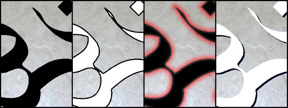
That’s a perfectly reasonable approach, but if you zoom in far enough on your texture, you’ll see some fuzzy stair-stepping as shown in the leftmost panel in Figure 7-5. The fuzziness can be alleviated by replacing blending with alpha testing (Alpha Testing), but the stair-stepping remains; see the middle panel.
You’ll almost always see stair-stepping when zooming in with bilinear filtering. Third-order texture filtering (also known as cubic filtering) would mitigate this, but it’s not easy to implement with OpenGL ES.
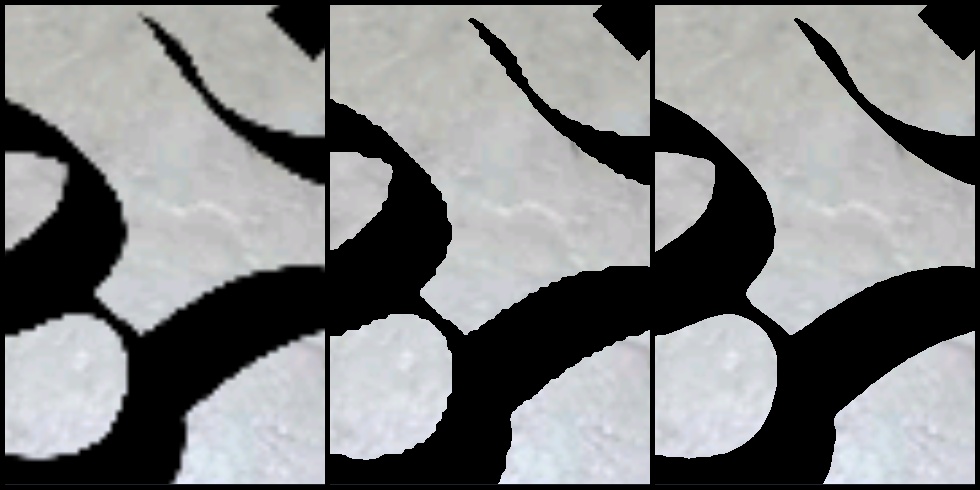
It turns out there’s a way to use bilinear filtering and achieve higher-quality results. The trick is to generate a signed distance field for your glyphs. A distance field is a grid of values, where each value represents the shortest distance from that grid cell to the glyph boundary. Cells that lie inside the glyph have negative values; cells that lie outside have positive values. If a grid cell lies exactly on the boundary of the glyph, it has a distance value of zero.
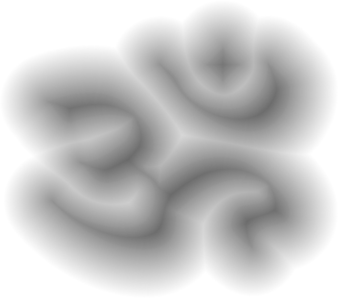
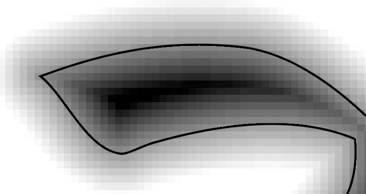
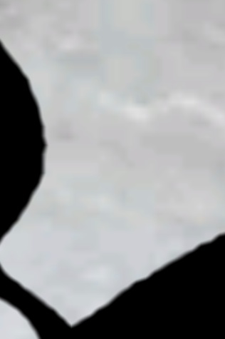
To represent a distance field in an OpenGL texture, we need a way to map from the signed distance values to grayscale. One approach is to represent a distance of zero as half-black (0.5) and then to choose maximum and minimum distances, which get mapped to 1.0 and 0. (This effectively clamps large distances, which is fine.) Figure 7-6 shows a distance field for the mystical Aum symbol. Figure 7-7 zooms in on a portion of the Aum distance field with the original glyph boundary represented as a black line.
The concept of a distance field may seem obscure, but it’s useful in many surprising ways. Not only does it provide a way to preserve quality of edges (with both ES 1.1 and ES 2.0), but it also makes it easy to apply a bevy of text effects, such as shadows and outlines (these are ES 2.0 only).
Generating Distance Fields with Python
Before diving in to the application of
distance fields, let’s take a look at how to generate them. The most
popular way of doing this is actually quite simple to implement, despite
having a ridiculously complex name: “the eight-points signed sequential
Euclidean distance transform algorithm,” or 8SSEDT for short. The basic
idea is to store a pair of integers at each grid cell
(dx and dy), which represents the
number of cells between it and the nearest cell on the opposite side of
the vector boundary. Each cell is initialized to either (0, 0) or (+∞,
+∞), depending on whether the cell is inside the vector. The algorithm
itself consists of “propagating” the distances by having each cell
compare its dx:dy pair to its neighbor and then adding it to the current
cell if it’s closer. To achieve a signed distance, the algorithm is run
on two separate grids and then merges the results.
Let’s momentarily go back to using Python and the PIL library since they provide a convenient environment for implementing the algorithm; see Example 7-9.
import os
import math
from PIL import Image

inside, outside = (0,0), (9999, 9999)

def invert(c):
    return 255 - c

def initCell(pixel):
    if pixel == 0: return inside
    return outside

def distSq(cell):
    return cell[0] * cell[0] + cell[1] * cell[1]

def getCell(grid, x, y):
    if y < 0 or y >= len(grid): return outside
    if x < 0 or x >= len(grid[y]): return outside
    return grid[y][x]

def compare(grid, cell, x, y, ox, oy):
    other = getCell(grid, x + ox, y + oy)
    other = (other[0] + ox, other[1] + oy)
    if distSq(other) < distSq(cell): return other
    return cell

def propagate(grid):
    height = len(grid)
    width = len(grid[0])
    for y in xrange(0, height):
        for x in xrange(0, width):
            cell = grid[y][x]
            cell = compare(grid, cell, x, y, -1,  0)
            cell = compare(grid, cell, x, y,  0, -1)
            cell = compare(grid, cell, x, y, -1, -1)
            cell = compare(grid, cell, x, y, +1, -1)
            grid[y][x] = cell
        for x in xrange(width - 1, -1, -1):
            cell = grid[y][x]
            cell = compare(grid, cell, x, y, 1, 0)
            grid[y][x] = cell
    for y in xrange(height - 1, -1, -1):
        for x in xrange(width - 1, -1, -1):
            cell = grid[y][x]
            cell = compare(grid, cell, x, y, +1,  0)
            cell = compare(grid, cell, x, y,  0, +1)
            cell = compare(grid, cell, x, y, -1, +1)
            cell = compare(grid, cell, x, y, +1, +1)
            grid[y][x] = cell
        for x in xrange(0, width):
            cell = grid[y][x]
            cell = compare(grid, cell, x, y, -1,  0)
            grid[y][x] = cell

def GenerateDistanceField(inFile, outFile, spread):

    print "Allocating the destination image..."
    image = Image.open(inFile)
    image.load()
    channels = image.split()
    if len(channels) == 4: alphaChannel = channels[3]
    else: alphaChannel = channels[0]
    w = alphaChannel.size[0] + spread * 2
    h = alphaChannel.size[1] + spread * 2
    img = Image.new("L", (w, h), 0)
    img.paste(alphaChannel, (spread, spread))
    width, height = img.size

    print "Creating the two grids..."
    pixels = img.load()
    grid0 = [[initCell(pixels[x, y]) \
              for x in xrange(width)] \
              for y in xrange(height)]
    grid1 = [[initCell(invert(pixels[x, y])) \
              for x in xrange(width)] \
              for y in xrange(height)]

    print "Propagating grids..."
    propagate(grid0)
    propagate(grid1)

    print "Subtracting grids..."
    signedDistance = [[0 for x in xrange(width)] for y in xrange(height)]
    for y in xrange(height):
        for x in xrange(width):
            dist1 = math.sqrt(distSq(grid0[y][x]))
            dist0 = math.sqrt(distSq(grid1[y][x]))
            signedDistance[y][x] = dist0 - dist1

    print "Normalizing..."
    maxDist, minDist = spread, -spread
    for y in xrange(height):
        for x in xrange(width):
            dist = signedDistance[y][x]
            if dist < 0: dist = -128 * (dist - minDist) / minDist
            else: dist = 128 + 128 * dist / maxDist
            if dist < 0: dist = 0
            elif dist > 255: dist = 255
            signedDistance[y][x] = int(dist)
            pixels[x, y] = signedDistance[y][x]

    print "Saving %s..." % outFile
    img.save(outFile)

if __name__ == "__main__":
    inFile, outFile = 'Aum.png', 'DistanceFieldAum.png'
    GenerateDistanceField(inFile, outFile, spread = 15)
Don’t let Example 7-9 scare you! You’re in good shape if you simply grok the concept of a distance field. The formal proof of the generation algorithm is beyond the scope of this book, but you can always flip back to Generating Distance Fields with Python to review it at a high level.
Use Distance Fields Under ES 1.1 with Alpha Testing
To make use of a distance field with iPhone models that support only OpenGL ES 1.1, simply bind the distance field texture and enable alpha testing with a threshold value of 0.5:
glDisable(GL_BLEND);
glEnable(GL_ALPHA_TEST);
glAlphaFunc(GL_LESS, 0.5);
Remember, blending applies an equation at every pixel to determine the final color, while alpha testing compares the source alpha with a given value and leaves the framebuffer unchanged if the comparison fails.
Adding Text Effects with Fragment Shaders
One of the reasons I love distance fields is that they enable more than quality enhancements. On iPhone models that support OpenGL ES 2.0, distance fields can be used in conjunction with a fragment shader to achieve a variety of special effects, all using the same source bitmap. See Figure 7-8.
Smoothing and Derivatives
The first distance field effect that I want to cover is smoothing, as shown in the leftmost panel in Figure 7-8.
Go back and take another look at the big stair steps in the left-most panel in Figure 7-5; they correspond to the texels in the source image. Alpha testing with a distance field fixed this up (rightmost panel), but it still exhibits pixel-level aliasing. This is because the rasterized pixels are always either fully lit or discarded; there are no shades of gray. We can fix this up with a fragment shader.
Before diving into the shader code, let’s
take a look at GLSL’s smoothstep function. Here’s the
declaration:
float smoothstep(float edge0, float edge1, float x)
smoothstep returns 0.0 if
x is less than or equal to edge0
and returns 1.0 if x is greater than or equal to
edge1. If x is between these two
values, then it interpolates between 0 and 1. Calling
smoothstep is equivalent to the following:
float t = clamp ((x – edge0) / (edge1 – edge0), 0.0, 1.0);
return t * t * (3.0 – 2.0 * t);
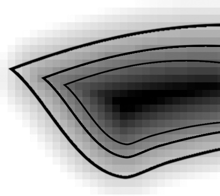
To see how smoothstep
comes in handy for smoothing, visualize two new boundary lines in the
distance field: one at edge0 (a deflated version of
the glyph), the other at edge1 (an inflated version
of the glyph). See Figure 7-9; the middle
line is the region where distance = 0.
Alpha should be opaque at
edge0 and transparent at edge1. To
achieve smoothing, the fragment shader needs to create an alpha ramp
between these two boundaries. Example 7-10
shows an implementation.
varying mediump vec2 TextureCoord;

uniform sampler2D DistanceField;
uniform mediump vec3 GlyphColor;

const mediump float SmoothCenter = 0.5;
const mediump float SmoothWidth = 0.04;

void main(void)
{
    mediump vec4 color = texture2D(DistanceField, TextureCoord);
    mediump float distance = color.a;
    mediump float alpha = smoothstep(SmoothCenter - SmoothWidth,
                                     SmoothCenter + SmoothWidth,
                                     distance);
    gl_FragColor = vec4(GlyphColor, alpha);
}
The fragment shader in Example 7-10 is fairly easy to understand, but
unfortunately it suffers from a fundamental flaw. The value of
SmoothWidth is always the same, regardless of how
much the glyph is magnified. As a result, anti-aliasing is too blurry
when the camera is near the texture (Figure 7-10), and it’s ineffective when the camera is
very far away.
Fortunately, the iPhone supports a fragment shader extension to help out with this. Unfortunately, it’s not supported in the simulator at the time of this writing.
Note
It’s easy to deal with this disparity. At runtime, check for extension support using the method described in Dealing with Size Constraints. Compile fragment shader A if it’s supported; otherwise, compile fragment shader B.
The name of this extension is
OES_standard_derivatives. That’s right,
“derivatives.” Don’t run in fear if this conjures up images of a brutal
calculus professor! It’s not as bad as it sounds. The extension simply
adds three new functions to GLSL:
float dFdx(float f);
float dFdy(float f);
float fwidth(float f)
These functions are available only to the
fragment shader. They return a value proportional to the rate of change
of the argument when compared to neighboring pixels. The
dFdx function returns a rate of change along the
x-axis; the dFdy function returns a rate of change
along the y-axis. The fwidth function provides a
convenient way of combining the two values:
fwidth(f) = abs(dFdx(f)) + abs(dFdy(f))
In our case, when the camera is far away, the rate of change in the on-screen distance field is greater than when the camera is close-up. To achieve consistent anti-aliasing, we’ll simply use a larger filter width when the camera is far away. See Example 7-11 for a new version of the fragment shader that uses derivatives.
#extension GL_OES_standard_derivatives : enable

varying mediump vec2 TextureCoord;

uniform sampler2D DistanceField;
uniform mediump vec3 GlyphColor;

const mediump float SmoothCenter = 0.5;

void main(void)
{
    mediump vec4 color = texture2D(DistanceField, TextureCoord);
    mediump float distance = color.a;
    mediump float smoothWidth = fwidth(distance);
    mediump float alpha = smoothstep(SmoothCenter - smoothWidth,
                                     SmoothCenter + smoothWidth, distance);
    gl_FragColor = vec4(GlyphColor, alpha);
}
Implementing Outline, Glow, and Shadow Effects
Using shaders with distance fields can also
achieve a variety of special effects, as shown in Figure 7-8. In the interest of brevity, I won’t go
into too much detail here; much like the smoothing example from the
previous section, all these effects rely on using
smoothstep and various offsets from the
distance=0 boundary. They also make use of a GLSL
function called mix; here’s its
declaration:
float mix(float x, float y, float a)
You probably already guessed that this function performs linear interpolation between its first two arguments:
mix(x, y, a) = x * (1 - a) + y * a
See Example 7-12 for an “übershader” that can
produce any of the aforementioned distance field effects, depending on
how the application sets up the uniforms. If you’re trying to run this
shader on the simulator, you’ll need to remove the top line and replace
the fwidth function with a constant.
Note
As always, you can obtain the complete
source for an app that demonstrates this technique from this
book’s website. The sample in this case is simply called
“DistanceField,” and it uses #ifdef to
automatically avoid derivatives when running in the simulator.
#extension GL_OES_standard_derivatives : enable varying mediump vec2 TextureCoord; uniform sampler2D DistanceField; uniform mediump vec3 OutlineColor; uniform mediump vec3 GlyphColor; uniform mediump vec3 GlowColor; uniform bool Outline;
-
The
Outline,Glow, andShadowbooleans are set from the application to choose which effect to apply. (An alternative strategy would be splitting this into three separate shaders.)-
This is the offset of the shadow from the glyph. In this case, the aspect ratio of the texture is 2:1, so the X offset is half the size the Y offset. Note that you may need to negate the X or Y value, depending on how your distance field is oriented.
-
-
SmoothCenteris the alpha value that represents the distance = 0 boundary.-
OutlineCentertells the shader how far from the glyph edge to render the outline. For an outline that is just inside the glyph, this value should be less than 0.5.-
GlowBoundarytells the shader how far out to extend the glow. To create a pulsing glow, change this into a uniform, and cycle its value from within the application code.
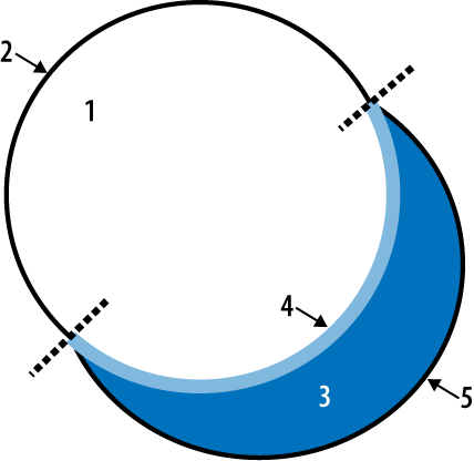
The shadow effect in Example 7-12 deserves further explanation. It applies anti-aliasing to the transition not only between the vector and the background but also between the shadow and the background and between the vector and the shadow. The shader pulls this off by deciding which of the following five regions the pixel falls into (see Figure 7-11):
Animation with Sprite Sheets
Let’s set aside glyph rendering and visit another topic common to 2D graphics: sprites. The iPhone is an ideal platform for casual gaming, and many popular iPhone games rely heavily on sprites for frame composition. To recap, a sprite is simply a bitmap that gets applied to a rectangular region of the screen. Sprites often use alpha to allow the background (and possibly other sprites) to show through. I like to think of sprite rendering as using an overhead projector, where each sprite is a plastic sheet with a cartoon drawing.
For efficiency, it’s common to pack a slew of sprites into a single texture; this is called a sprite sheet. In general, a texture that contains multiple disparate images is known as a texture atlas. The numerals texture presented in Text Rendering 101: Drawing an FPS Counter was an example of a texture atlas.
Note
There are tools out there to help you build sprite sheets. One such tool is a web-based application called zwopple by Robert Payne. You can find it at http://zwoptex.zwopple.com.
Recall that there are two ways of animating a sprite: the screen position can change (for example, a bouncing ball), or the source image can change (for example, a spinning ball). In the former case, the application code updates the vertex positions at every frame; in the latter case, the application updates the texture coordinates at every frame.
For an example of a sprite with multiple animation frames, see Figure 7-12, a sprite sheet from a game that I created in my college days. (The game’s protagonist is named Noop, a blobby fellow who moves horizontally by repeatedly squishing his legs together in wormlike fashion.)
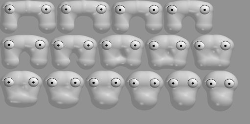
Image Composition and a Taste of Multitexturing
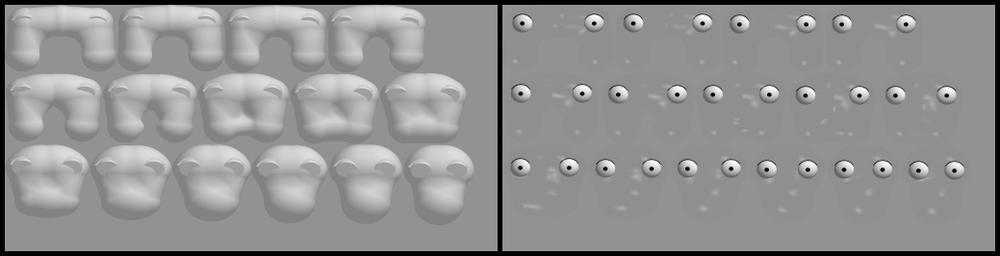
Sometimes it’s desirable to split a sprite sheet into multiple layers, as shown in Figure 7-13. The left sheet has the animation frames for Noop’s body; the right sheet has his eyes and shiny highlights. This allows the application to vary the colors of the layers independently. For example, my game can draw Noop using a yellowish hue most of the time but sometimes renders him in orange to convey that he’s hurt. In both cases, the eyes and highlights are white.
We discussed how to shift the apparent color of
a texture in Shifting Texture Color with Per-Vertex Color. You can use a
luminance or luminance-alpha texture rather than a full-blown RGBA texture
and then modulate the texture’s color using per-vertex color (for example,
by calling glColor4f).
The obvious way of composing Noop’s eyes with his body is to render the same quad in two passes with blending enabled. The first pass uses texture coordinates for the body; the second pass uses coordinates for the eyes and highlights. Example 7-13 shows an example of this procedure.
// Enable Blending:
glEnable(GL_BLEND);
glBlendFunc(GL_SRC_ALPHA, GL_ONE_MINUS_SRC_ALPHA);

// Draw Noop's body in a yellowish hue:
glColor4f(1, 0.83f, 0.33f, 1);
glBindTexture(GL_TEXTURE_2D, bodyTexture);
glTexParameteriv(GL_TEXTURE_2D, GL_TEXTURE_CROP_RECT_OES, sourceRectangle);
glDrawTexfOES(x, y, 0, width, height);

// Draw Noop's eyes in white:
glColor4f(1, 1, 1, 1);
glBindTexture(GL_TEXTURE_2D, eyesTexture);
glTexParameteriv(GL_TEXTURE_2D, GL_TEXTURE_CROP_RECT_OES, sourceRectangle);
glDrawTexfOES(x, y, 0, width, height);
Note that Example 7-13 is
valid only for ES 1.1; under ES 2.0, we need to replace the
DrawTex-related lines with calls to glDrawArrays or
glDrawElements, and we need to replace
glColor4f with glVertexAttrib4f. See
Example 7-14.
// Enable Blending:
glEnable(GL_BLEND);
glBlendFunc(GL_SRC_ALPHA, GL_ONE_MINUS_SRC_ALPHA);

// Draw Noop's body in a yellowish hue:
glVertexAttrib4f(MyColorAttribute, 1, 0.83f, 0.33f, 1);
glBindTexture(GL_TEXTURE_2D, bodyTexture);
glDrawArrays(GL_TRIANGLES, 0, 6); // draw a rectangle with two triangles

// Draw Noop's eyes in white:
glVertexAttrib4f(MyColorAttribute, 1, 1, 1, 1);
glBindTexture(GL_TEXTURE_2D, eyesTexture);
glDrawArrays(GL_TRIANGLES, 0, 6); // draw a rectangle with two triangles
Both OpenGL ES 1.1 and ES 2.0 provide a way to
combine simple two-pass operations like this into a single draw call. It’s
called multitexturing. Multitexturing allows you to
set up more than one texture stage. Example 7-15 shows the sample code for rendering Noop with
multitexturing; note there’s only one call to
glDrawTexfOES.
glColor4f(1, 0.83f, 0.33f, 1);
glActiveTexture(GL_TEXTURE0);
glEnable(GL_TEXTURE_2D);
glBindTexture(GL_TEXTURE_2D, bodyTexture);
glTexParameteriv(GL_TEXTURE_2D, GL_TEXTURE_CROP_RECT_OES, sourceRectangle);

glActiveTexture(GL_TEXTURE1);
glEnable(GL_TEXTURE_2D);
glBindTexture(GL_TEXTURE_2D, eyesTexture);
glTexParameteriv(GL_TEXTURE_2D, GL_TEXTURE_CROP_RECT_OES, sourceRectangle);
glDrawTexfOES(x, y, 0, width, height);
The key lines in Example 7-15
are the calls to glActiveTexture, which sets the
current texture stage and affects all subsequent texture-related calls,
including glEnable(GL_TEXTURE_2D).
This allows individual stages to be independently turned on or
off.
I should warn you that Example 7-15 alone is not quite enough; you also need to tell OpenGL how to combine the color values from the two texture stages. With ES 1.1, this is quite a hassle; see Example 7-16. This sets up the second texture stage so that it works in a way similar to typical alpha blending. Thankfully, you can often perform this type of configuration only once, when your application first starts up.
glActiveTexture(GL_TEXTURE1);
glTexEnvi(GL_TEXTURE_ENV, GL_TEXTURE_ENV_MODE, GL_COMBINE);
glTexEnvi(GL_TEXTURE_ENV, GL_COMBINE_RGB, GL_INTERPOLATE);
glTexEnvi(GL_TEXTURE_ENV, GL_SRC0_RGB, GL_TEXTURE);
glTexEnvi(GL_TEXTURE_ENV, GL_OPERAND0_RGB, GL_SRC_COLOR);
glTexEnvi(GL_TEXTURE_ENV, GL_SRC1_RGB, GL_PREVIOUS);
glTexEnvi(GL_TEXTURE_ENV, GL_OPERAND1_RGB, GL_SRC_COLOR);
glTexEnvi(GL_TEXTURE_ENV, GL_SRC2_RGB, GL_TEXTURE);
glTexEnvi(GL_TEXTURE_ENV, GL_OPERAND2_RGB, GL_SRC_ALPHA);
glTexEnvi(GL_TEXTURE_ENV, GL_COMBINE_ALPHA, GL_REPLACE);
glTexEnvi(GL_TEXTURE_ENV, GL_SRC0_ALPHA, GL_PREVIOUS);
glTexEnvi(GL_TEXTURE_ENV, GL_OPERAND0_ALPHA, GL_SRC_ALPHA);
OpenGL ES 2.0 simplifies this by allowing you
to combine colors from within your fragment shader. We’ll discuss this
further in the next chapter, and I’ll explain glTexEnv in greater detail—I just wanted to
whet your appetite!
Mixing OpenGL ES and UIKit
Sprites are often used for rendering
interactive widgets in a HUD (see Handling the Heads-Up Display).
Handling mouse interaction can be a chore when you don’t have a UI
framework to stand upon. If you’re developing a 3D application and find
yourself yearning for UIKit, don’t dismiss it right away. It’s true that
mixing UIKit and OpenGL ES is generally ill-advised for performance
reasons, but in many situations, it’s the right way to go. This is
especially true with 3D applications that aren’t as graphically demanding
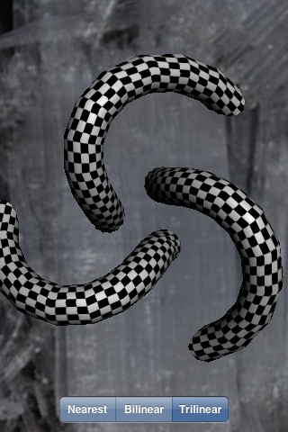
as huge, professionally produced games. Figure 7-14
depicts an application that overlays a UISegmentedControl widget with a 3D
scene.
The full source code for the application depicted in Figure 7-14 is available from this book’s site under the name CocoaMix. You might also want to check out the PVRTextureLoader sample from Apple’s SDK, which includes a slick sliding animation for a panel of UIKit controls.
Note
The performance of “mixed” rendering has been improving as Apple rolls out new devices and new revisions to the iPhone OS. By the time you read this, using nonanimated UIKit controls in conjunction with OpenGL might be a perfectly acceptable practice.
Recall that all OpenGL rendering takes place in
a UIView-derived class; every sample in this book
defines a class called GLView for this purpose. Adding
a few simple controls to GLView is fairly painless, so
let’s try adding a UISegmentedControl that selects a
texture minification filter.
First we need to add a field to the
GLView class declaration for the new control. See the
bold line in Example 7-17.
#import "Interfaces.hpp"
#import <UIKit/UIKit.h>
#import <QuartzCore/QuartzCore.h>

@interface GLView : UIView {
@private
    IRenderingEngine* m_renderingEngine;
    IResourceManager* m_resourceManager;
    EAGLContext* m_context;
    float m_timestamp;
    UISegmentedControl* m_filterChooser;
}

- (void) drawView: (CADisplayLink*) displayLink;

@end
Next, we need to instance the control and create a method for event handling; see Example 7-18.
...

- (id) initWithFrame: (CGRect) frame
{
    if (self = [super initWithFrame:frame])
    {
        CAEAGLLayer* eaglLayer = (CAEAGLLayer*) self.layer;
        eaglLayer.opaque = YES;

        EAGLRenderingAPI api = kEAGLRenderingAPIOpenGLES1;
        m_context = [[EAGLContext alloc] initWithAPI:api];

        ...

        // Create and configure the UIKit control:

        NSArray* labels = [NSArray arrayWithObjects:@"Nearest",
                                                    @"Bilinear",
                                                    @"Trilinear", nil];

        m_filterChooser =
          [[[UISegmentedControl alloc] initWithItems:labels] autorelease];
        m_filterChooser.segmentedControlStyle = UISegmentedControlStyleBar;
        m_filterChooser.selectedSegmentIndex = 0;

        [m_filterChooser addTarget:self
                         action:@selector(changeFilter:)
                         forControlEvents:UIControlEventValueChanged];

        // Add the control to GLView's children:

        [self addSubview:m_filterChooser];

        // Position the UIKit control:

        const int ScreenWidth = CGRectGetWidth(frame);
        const int ScreenHeight = CGRectGetHeight(frame);
        const int Margin = 10;

        CGRect controlFrame = m_filterChooser.frame;
        controlFrame.origin.x = ScreenWidth / 2 - controlFrame.size.width / 2;
        controlFrame.origin.y = ScreenHeight - controlFrame.size.height - Margin;
        m_filterChooser.frame = controlFrame;
    }
    return self;
}

- (void) changeFilter: (id) sender
{
    TextureFilter filter = (TextureFilter) [sender selectedSegmentIndex];
    m_renderingEngine->SetFilter(filter);
}

...
Example 7-18 includes
some UIKit and Objective-C mechanisms that we haven’t seen before (such as
@selector), but it will be familiar to iPhone
developers. Check out Jonathan Zdziarski’s iPhone SDK
Application Development
(O’Reilly) to learn more about UIKit.
Note that you can also use UIKit to render
“look-alike” controls, rather than using the actual UIKit controls. For
example, you can render some buttons into a CGImage at
launch time and then create an OpenGL texture from that (see Generating and Transforming OpenGL Textures with Quartz). This would give your buttons
the look and feel of the iPhone’s native UI, plus it wouldn’t suffer from
the potential performance issues inherent in mixing the actual UIKit
control with OpenGL. The downside is that you’d need to implement the
interactivity by hand.
Rendering Confetti, Fireworks, and More: Point Sprites
You may find yourself wanting to render a system of particles that need a bit more pizzazz than mere single-pixel points of light. The first thing that might come to mind is rendering a small alpha-blended quad for each particle. This is a perfectly reasonable approach, but it requires you to come up with the coordinates for two textured triangles at each point.
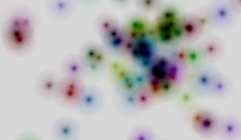
It turns out the iPhone supports an extension to make this much easier by enabling point sprites. Point sprites are small screen-aligned quads that get drawn at each vertex in a vertex array or VBO. For simplicity, a point sprite uses an entire texture; there’s no need to provide texture coordinates. This makes it a breeze to render particle systems such as the one depicted in Figure 7-15.
For OpenGL ES 1.1, the name of the extension is
GL_OES_point_sprite, and it allows you to make the
following function calls:
glEnable(GL_POINT_SPRITE_OES);
glDisable(GL_POINT_SPRITE_OES);
glTexEnvi(GL_POINT_SPRITE_OES, GL_COORD_REPLACE_OES, GL_TRUE);
glTexEnvi(GL_POINT_SPRITE_OES, GL_COORD_REPLACE_OES, GL_FALSE);
With OpenGL ES 2.0, point sprites are supported in the core specification rather than an extension. There’s no need to call any of these functions because point sprite functionality is implicit. You’ll see how to use point sprites in both ES 1.1 and ES 2.0 in the upcoming SpringyStars sample.
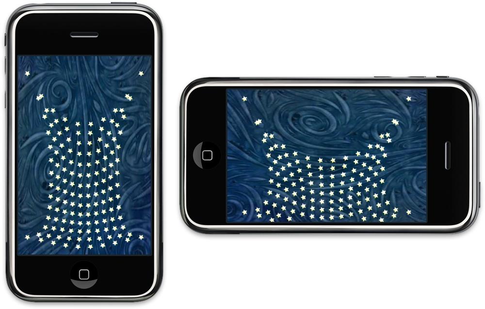
Chapter Finale: SpringyStars
To show off point sprites in action, let’s wrap up the chapter with a mass-spring simulation that renders a network of little white stars, as shown in Figure 7-16. The “star net” droops down in the direction of gravity according to how you’re holding the iPhone. You can find the complete source for this example from this book’s web page.
Physics Diversion: Mass-Spring System
Before we dive into the code, let’s take a
brief detour from graphics and review some physics. The easiest way to
create a simple physics simulation to call an
Update() method on every object in the simulation.
The update method has an argument for the time step, which represents
elapsed time since the previous call. (This isn’t much different from
the UpdateAnimation() method presented way back in
Chapter 1.) For our SpringyStars app, the pseudocode
for the update method looks like this:
void Update(float dt)
{
    Acceleration = TotalForces / Mass;
    Velocity += Acceleration * dt;
    Position += Velocity * dt;
}
The previous code snippet should make sense if you remember your high-school physics. Perhaps a bit foggier in your memory is Hooke’s law, which we’ll need for modeling the spring forces between the star sprites; see Equation 7-1.
F is the restoring force of the spring, so called because it represents the effort to restore the spring’s length to its rest position. You can think of the k constant as being the stiffness of the spring. x is the displacement between the current end of the spring and its rest position.
Note
To learn physics from a much more authoritative source, take a look at Physics for Game Developers (O’Reilly) by David Bourg.
Hooke’s law deals with only a single spring, but in our case we have a network of springs. Our simulation needs to maintain a list of “nodes” (rigid bodies), each of which is connected to a set of neighboring nodes. Here’s a code snippet that applies Hooke’s law to a node and its neighbor:
vec2 v = neighbor->position - this->position;
float length = v.Length();
vec2 direction = v.Normalized();
vec2 restoringForce = direction * StiffnessContant * (length - RestLength);
In the previous snippet, the
restoringForce vector applies to the
this node, while an equal and opposite force (that
is, -restoringForce) applies to the
neighbor node.
Taken alone, Hooke’s law can produce oscillations that last forever. To be more realistic, the simulation needs to include a damping force to subdue the spring’s effect. The damping force between two nodes is proportional to their relative velocity:
In this case, kd is a damping constant. Much like the stiffness constant in Hooke’s law, I find that the best way to come up with a reasonable value is through experimentation. (More rigorous mass-spring systems include a global damping force, but this is good enough for our purposes.)
The C++ code snippet for computing damping force looks like this:
vec2 relativeVelocity = neighbor->velocity - this->m_velocity;
vec2 dampingForce = relativeVelocity * DampingConstant;
At this point, we’re ready to design a C++ class to represent a star sprite in a simple mass-spring system. See Example 7-19.
#include <list>

class SpringNode;

typedef std::list<SpringNode*> NeighborList;

class SpringNode {
public:
    SpringNode()
    {
        m_position = vec2(0, 0);
        m_velocity = vec2(0, 0);
        m_mass = 1;
        m_pinned = false;
    }
    void Pin()
    {
        m_pinned = true;
    }
    void SetPosition(const vec2& p)
    {
        m_position = p;
    }
    vec2 GetPosition() const
    {
        return m_position;
    }
    void AddNeighbor(SpringNode* node)
    {
        m_neighbors.push_back(node);
    }
    void ResetForce(vec2 force)
    {
        m_force = force;
    }
    void ComputeForce()
    {
        const float StiffnessContant = 3.0f;
        const float RestLength = 0.075f;
        const float DampingConstant = 2.0f;

        NeighborList::const_iterator n = m_neighbors.begin();
        for (; n != m_neighbors.end(); ++n) {

            // Compute the spring force:
            vec2 v = (*n)->m_position - m_position;
            float length = v.Length();
            vec2 direction = v.Normalized();
            vec2 restoringForce = direction * StiffnessContant
              * (length - RestLength);

            // Compute the damping force:
            vec2 relativeVelocity = (*n)->m_velocity - m_velocity;
            vec2 dampingForce = relativeVelocity * DampingConstant;

            // Add the two forces to this node and subtract them
            // from the neighbor:
            vec2 totalForce = restoringForce + dampingForce;
            m_force += totalForce;
            (*n)->m_force -= totalForce;
        }
    }
    void Update(float dt)
    {
        if (m_pinned)
            return;

        vec2 acceleration = m_force / m_mass;
        m_velocity += acceleration * dt;
        m_position += m_velocity * dt;
    }
private:
    vec2 m_force;
    vec2 m_position;
    vec2 m_velocity;
    float m_mass;
    bool m_pinned;
    NeighborList m_neighbors;
};
Note the boolean field called
m_pinned, which causes a node to be impervious to the
forces acted upon it. We’ll use this to affix the four corners of the
net to their starting positions. This prevents the net from falling off
the screen.
Speaking of falling off the screen, note that
there’s nothing obvious in Example 7-19 that takes
gravity into account. That’s because the application can use the
ResetForce() method to
initialize the m_force field to the gravity vector
and then call ComputeForce() in
a separate pass to add in all the relevant spring forces. The simulation
will perform three separate passes through the node list; see the
pseudocode in Example 7-20. (Don’t combine these
into a single loop.)
C++ Interfaces and GLView
To avoid code duplication between the ES 2.0
and ES 1.1 backends, let’s put the physics into the application engine
and pass it a normalized 2D vector for the direction of gravity. As a
result, the IRenderingEngine interface is very
simple; see Example 7-21.
#pragma once
#include "Vector.hpp"
#include <vector>

typedef std::vector<vec2> PositionList;

struct IApplicationEngine {
    virtual void Initialize(int width, int height) = 0;
    virtual void Render() const = 0;
    virtual void UpdateAnimation(float timeStep) = 0;
    virtual void SetGravityDirection(vec2 direction) = 0;
    virtual ~IApplicationEngine() {}
};

struct IRenderingEngine {
    virtual void Initialize() = 0;
    virtual void Render(const PositionList& positions) const = 0;
    virtual ~IRenderingEngine() {}
};

IApplicationEngine* CreateApplicationEngine(IRenderingEngine*);

namespace ES1 { IRenderingEngine* CreateRenderingEngine(); }
namespace ES2 { IRenderingEngine* CreateRenderingEngine(); }
The GLView class looks
much like all the other samples in this book, except that it needs to
pass in a gravity vector. See Example 7-22.
For more information about setting up the accelerometer, flip back to
the section Replacing Buttons with Orientation Sensors.
ApplicationEngine Implementation
See Example 7-23
for the application engine implementation. Recall that the
GLView class calls UpdateAnimation
according to the refresh rate of the display. This provides enough time
to perform several simulation iterations, each using a small time step.
Performing several small iterations produces more accurate results than
a single iteration with a large time step. In fact, an overly large time
step can cause the simulation to go ballistic.
Warning
Updating the physics along with the
rendering is a bit of a hack but good enough for our purposes. For a
production-quality application, you might want to create a timer
object in your GLView class just for
physics.
#include "Interfaces.hpp"
#include "SpringNode.hpp"

using namespace std;

class ApplicationEngine : public IApplicationEngine {
public:
    ApplicationEngine(IRenderingEngine* renderingEngine);
    ~ApplicationEngine();
    void Initialize(int width, int height);
    void SetGravityDirection(vec2 direction);
    void Render() const;
    void UpdateAnimation(float dt);
private:
    vec2 m_gravityDirection;
    vector<SpringNode> m_springNodes;
    PositionList m_positions;
    IRenderingEngine* m_renderingEngine;
};

IApplicationEngine* CreateApplicationEngine
  (IRenderingEngine* renderingEngine)
{
    return new ApplicationEngine(renderingEngine);
}

ApplicationEngine::~ApplicationEngine()
{
    delete m_renderingEngine;
}

void ApplicationEngine::Initialize(int width, int height)
{
    m_renderingEngine->Initialize();
}

void ApplicationEngine::SetGravityDirection(vec2 direction)
{
    m_gravityDirection = direction;
}

void ApplicationEngine::Render() const
{
    m_renderingEngine->Render(m_positions);
}

ApplicationEngine::ApplicationEngine(IRenderingEngine* renderingEngine) :
    m_renderingEngine(renderingEngine),
    m_gravityDirection(vec2(0, -1))
{
    const int NumColumns = 10;
    const int NumRows = 14;
    const float SpreadFactor = 0.125f;

    m_springNodes.resize(NumColumns * NumRows);
    m_positions.resize(m_springNodes.size());

    vector<SpringNode>::iterator node = m_springNodes.begin();
    for (int r = 0; r < NumRows; ++r) {
        for (int c = 0; c < NumColumns; ++c) {

            vec2 position;
            position.x = c - (NumColumns - 1) / 2.0f;
            position.y = r - (NumRows - 1) / 2.0f;
            node->SetPosition(position * SpreadFactor);

            if (c > 0)
                node->AddNeighbor(&*node - 1);

            if (r > 0)
                node->AddNeighbor(&*node - NumColumns);

            ++node;
        }
    }

    m_springNodes[0].Pin();
    m_springNodes[NumColumns - 1].Pin();
    m_springNodes[NumColumns * NumRows - 1].Pin();
    m_springNodes[NumColumns * (NumRows - 1)].Pin();

    UpdateAnimation(0);
}

void ApplicationEngine::UpdateAnimation(float dt)
{
    const float GravityStrength = 0.01f;
    const int SimulationIterations = 10;

    vector<SpringNode>::iterator node;
    vec2 force = m_gravityDirection * GravityStrength;

    for (int i = 0; i < SimulationIterations; ++i) {
        for (node = m_springNodes.begin();
             node != m_springNodes.end();
             ++node)
            node->ResetForce(force);

        for (node = m_springNodes.begin();
             node != m_springNodes.end();
             ++node)
            node->ComputeForce();

        PositionList::iterator position = m_positions.begin();
        for (node = m_springNodes.begin();
             node != m_springNodes.end();
             ++node)
        {
            node->Update(dt);
            *position++ = node->GetPosition();
        }
    }
}
-
The
m_gravityDirectionfield stores the normalized direction provided by theGLViewlayer.-
The
m_springNodesvector stores the rigid bodies in the simulation.-
The
m_positionsvector provides a contiguous list of node positions to the rendering engine.-
The
NumColumns,NumPositions, andSpreadFactorconstants determine the initial layout of the star sprites.-
-
Add a connection to the node to the left. The &* prefix converts an STL iterator into a vanilla pointer.
-
-
-
Call
UpdateAnimationonce at startup to initialize the position list.-
The gravity direction vector is normalized, so it needs to be scaled by the
GravityStrengthconstant before passing it in as a force vector.-
As mentioned earlier, we make several passes through the simulation loop for increased precision.
-
The contents of this loop corresponds to pseudocode in Example 7-20.
-
Copy the node position into the vertex array that gets passed to the rendering engine.
OpenGL ES 1.1 Rendering Engine and Additive Blending
One difficulty you might come across with point sprites is the order-dependency problem imposed by some blending equations (flip back to the section Blending Caveats to review this issue). One way to avoid this is to use additive blending. Here’s how to set it up:
glBlendFunc(GL_SRC_ALPHA, GL_ONE);
This sets up the following equation:
You can see how this differs from traditional blending because it can only make the framebuffer color brighter and brighter as more sprites are rendered. This produces an effect that may be desirable anyway; for example, if you’re rendering fireworks with a dense cloud of point sprites, additive blending helps vary the brightness and make the scene more interesting.
Recall that the
IRenderingEngine interface has only two methods;
Example 7-24 shows the ES 1.1 implementations of
these. The remainder of the file is much the same as other samples in
this book. For the full source, download the code from this
book’s website.
void RenderingEngine::Initialize()
{
    // Load up some textures:
    m_textures.Star = CreateTexture(Star);
    m_textures.Background = CreateTexture(_Background_pvrtc);

    // Extract width and height from the color buffer:
    ivec2 screenSize;
    glGetRenderbufferParameterivOES(GL_RENDERBUFFER_OES,
                                    GL_RENDERBUFFER_WIDTH_OES,
                                    &screenSize.x);
    glGetRenderbufferParameterivOES(GL_RENDERBUFFER_OES,
                                    GL_RENDERBUFFER_HEIGHT_OES,
                                    &screenSize.y);

    // Create the on-screen FBO:
    glGenFramebuffersOES(1, &m_framebuffers.Screen);
    glBindFramebufferOES(GL_FRAMEBUFFER_OES, m_framebuffers.Screen);
    glFramebufferRenderbufferOES(GL_FRAMEBUFFER_OES,
                                 GL_COLOR_ATTACHMENT0_OES,
                                 GL_RENDERBUFFER_OES,
                                 m_renderbuffers.Screen);

    // Set up various OpenGL state:
    glViewport(0, 0, screenSize.x, screenSize.y);
    glEnable(GL_TEXTURE_2D);
    glPointSize(15);
    glBlendFunc(GL_SRC_ALPHA, GL_ONE);

    // Set up the transforms:
    glMatrixMode(GL_PROJECTION);
    glLoadIdentity();

    const float NearPlane = 5, FarPlane = 100;
    const float Scale = 0.0005;
    glFrustumf(-Scale * screenSize.x / 2, Scale * screenSize.x / 2,
               -Scale * screenSize.y / 2, Scale * screenSize.y / 2,
               NearPlane, FarPlane);

    glMatrixMode(GL_MODELVIEW);

    vec3 eye(0, 0, 40);
    vec3 target(0, 0, 0);
    vec3 up(0, 1, 0);
    mat4 modelview = mat4::LookAt(eye, target, up);
    glLoadMatrixf(modelview.Pointer());
}

void RenderingEngine::Render(const PositionList& positions) const
{
    // Render the background:
    int backgroundRectangle[] = { 0, 0, 480, 320 };
    glTexParameteriv(GL_TEXTURE_2D,
                     GL_TEXTURE_CROP_RECT_OES,
                     backgroundRectangle);
    glBindTexture(GL_TEXTURE_2D, m_textures.Background);
    glColor4f(0.75, 0.75, 0.75, 1);
    glDrawTexfOES(0, 0, 0, 320, 480);

    // Set the state for point rendering:
    glEnable(GL_BLEND);
    glEnable(GL_POINT_SPRITE_OES);
    glTexEnvi(GL_POINT_SPRITE_OES, GL_COORD_REPLACE_OES, GL_TRUE);

    // Set up the vertex array:
    glEnableClientState(GL_VERTEX_ARRAY);
    glVertexPointer(2, GL_FLOAT, sizeof(vec2), &positions[0].x);

    // Render the point sprites:
    glBindTexture(GL_TEXTURE_2D, m_textures.Star);
    glColor4f(1, 1, 1, 1);
    glDrawArrays(GL_POINTS, 0, positions.size());

    // Restore the OpenGL state:
    glDisable(GL_BLEND);
    glDisable(GL_POINT_SPRITE_OES);
    glTexEnvi(GL_POINT_SPRITE_OES, GL_COORD_REPLACE_OES, GL_FALSE);
}
The only new OpenGL function in Example 7-24 is glPointSize. This
sets the width (and height) of the point sprites. OpenGL uses the
current model-view matrix to determine the distance of each point sprite
from the camera and shrinks the size of distant point sprites. This
effect can be abrogated like this:
float params[] = { 1, 0, 0 };
glPointParameterfv(GL_POINT_DISTANCE_ATTENUATION, params);
This seems rather obscure, but it has to do with how OpenGL computes the point size:
actualSize = desiredSize / sqrt(p[0] + p[1] * d + p[2] * d * d)
In the previous formula,
desiredSize is what you pass to
glPointSize, d is the distance
from the camera, and p is the array of values passed
to glPointParameterfv. (I’ve simplified this a bit by
leaving out some clamping that can occur.) In my opinion, the API
designers made this a bit too complex!
Note
You can even vary the size of the point
sprites on a per-vertex basis through the use of the
OES_point_size_array extension, which is supported
on all iPhone models.
OpenGL ES 2.0 handles point size quite differently from ES 1.1, which brings us to the next section.
Point Sprites with OpenGL ES 2.0
Before going over the C++ code for the ES 2.0 rendering engine, let’s take a look at the shaders. See Examples 7-25 and 7-26.
You’ve probably noticed that all built-in
variables can be recognized by their gl_ prefix.
There are two new built-in variables introduced in the previous
listings: gl_PointSize (written to by the vertex
shader) and gl_PointCoord (fed into the fragment
shader).
OpenGL ES 2.0 requires you to set up the point size from the vertex shader rather than the application code, which gives you the option to compute it dynamically; if you want, you can evaluate the same distance formula that ES 1.1 does. Or, you can do something much simpler, like what we’re doing here.
The gl_PointCoord variable
gives you the autocomputed texture coordinate that varies across the
point sprite. That’s why ES 2.0 doesn’t require you to call
glTexEnvi with GL_COORD_REPLACE;
it’s implicit in your fragment shader.
void RenderingEngine::Initialize()
{
    // Load up some textures:
    m_textures.Star = CreateTexture(Star);
    m_textures.Background = CreateTexture(_Background_pvrtc);

    // Extract width and height from the color buffer.
    glGetRenderbufferParameteriv(GL_RENDERBUFFER,
                                 GL_RENDERBUFFER_WIDTH, &m_screenSize.x);
    glGetRenderbufferParameteriv(GL_RENDERBUFFER,
                                 GL_RENDERBUFFER_HEIGHT, &m_screenSize.y);

    // Create the on-screen FBO.
    glGenFramebuffers(1, &m_framebuffers.Screen);
    glBindFramebuffer(GL_FRAMEBUFFER, m_framebuffers.Screen);
    glFramebufferRenderbuffer(GL_FRAMEBUFFER, GL_COLOR_ATTACHMENT0,
                              GL_RENDERBUFFER, m_renderbuffers.Screen);

    // Create the GLSL program.
    GLuint program = BuildProgram(SimpleVertexShader, SimpleFragmentShader);
    glUseProgram(program);

    // Extract the handles to attributes and uniforms.
    m_attributes.Position = glGetAttribLocation(program, "Position");
    m_attributes.TextureCoord = glGetAttribLocation(program, "TextureCoord");
    m_uniforms.Projection = glGetUniformLocation(program, "Projection");
    m_uniforms.Modelview = glGetUniformLocation(program, "Modelview");
    m_uniforms.Sampler = glGetUniformLocation(program, "Sampler");
    m_uniforms.IsSprite = glGetUniformLocation(program, "IsSprite");

    // Set up various GL state.
    glViewport(0, 0, m_screenSize.x, m_screenSize.y);
    glBlendFunc(GL_SRC_ALPHA, GL_ONE);

    // Set up the transforms.
    const float NearPlane = 5, FarPlane = 100;
    const float Scale = 0.0005;
    const float HalfWidth = Scale * m_screenSize.x / 2;
    const float HalfHeight = Scale * m_screenSize.y / 2;

    mat4 projection = mat4::Frustum(-HalfWidth, HalfWidth,
                                    -HalfHeight, HalfHeight,
                                    NearPlane, FarPlane);
    glUniformMatrix4fv(m_uniforms.Projection, 1, 0, projection.Pointer());

    vec3 eye(0, 0, 40);
    vec3 target(0, 0, 0);
    vec3 up(0, 1, 0);
    mat4 modelview = mat4::LookAt(eye, target, up);
    glUniformMatrix4fv(m_uniforms.Modelview, 1, 0, modelview.Pointer());
}

void RenderingEngine::Render(const PositionList& positions) const
{

    RenderBackground();

    glBindTexture(GL_TEXTURE_2D, m_textures.Star);
    glEnableVertexAttribArray(m_attributes.Position);
    glDisableVertexAttribArray(m_attributes.TextureCoord);
    glUniform1i(m_uniforms.IsSprite, GL_TRUE);

    glVertexAttribPointer(m_attributes.Position,
                          2,
                          GL_FLOAT,
                          GL_FALSE,
                          sizeof(vec2),
                          &positions[0].x);

    glEnable(GL_BLEND);
    glDrawArrays(GL_POINTS, 0, positions.size());
    glDisable(GL_BLEND);
}
Wrapping Up
This chapter has shown that OpenGL is quite adept at 2D rendering, even though most developers primarily think of it as a 3D graphics API.
If you’ve made it this far in this book, you’re
more than ready to make an entry into the world of 3D iPhone programming;
subsequent chapters will cover more advanced material. Recall that we gave
a brief taste of multitexturing and the glTexEnv
function in this chapter—we’ll go over these concepts in further detail in
the next chapter, along with a bevy of other advanced effects.
Get iPhone 3D Programming now with the O’Reilly learning platform.
O’Reilly members experience books, live events, courses curated by job role, and more from O’Reilly and nearly 200 top publishers.

