10.6 COMBINED PIPELINING AND PARALLEL PROCESSING FOR IIR FILTERS
Pipelining and parallel processing can also be combined for IIR filters to achieve a speedup in sample rate by a factor L × M, where L denotes the levels of block processing and M denotes stages of pipelining, or to achieve power reduction at the same speed.
Example 10.6.1 Consider the 1st-order IIR filter with transfer function
![]()
Derive the filter structure with 4-level pipelining and 3-level block processing, i.e., M = 4 and L = 3.
Because the filter order is 1, only 1 loop update operation is required. The other 3 outputs can be computed incrementally. Since pipelining level M =4, the loop must contain 4 delay elements, as shown in Fig. 10.21. Since the block
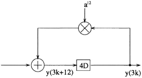
Fig. 10.21 Loop update for the pipelined block system.
size L= 3, each delay element represents a block delay, which corresponds to 3 sample delays. Therefore, y(3k + 12) needs to be expressed in terms of y(3k) and inputs (see Fig. 10.21). This can be done using look-ahead as follows:
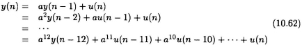
Substituting n = 3k + 12, we get:
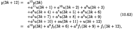
in which
The parallel-pipelined filter ...
Get VLSI Digital Signal Processing Systems: Design and Implementation now with the O’Reilly learning platform.
O’Reilly members experience books, live events, courses curated by job role, and more from O’Reilly and nearly 200 top publishers.

