The PIX in Action
Figure 9-1 is a diagram of where to install the PIX firewall on a standard network topological map.
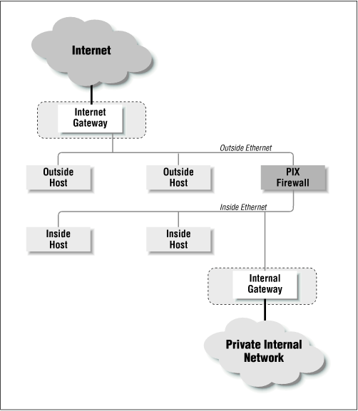
Figure 9-1. A typical PIX firewall setup
Functionally, the PIX firewall is set up much like a packet filtration router. The two Ethernet interfaces are labeled “outside” and “inside” for the two networks that you will need to connect it to. In Figure 9-1, the PIX firewall is situated on the “perimeter network” between the internal router and the external router. You will notice that the only machine connecting both networks is the PIX firewall. By funneling traffic through the PIX, you can construct an effective security gateway.
For the purpose of illustrating some of the sample configurations in this chapter, we will assume that the topology of our network looks like the one depicted in Figure 9-2.
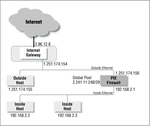
Figure 9-2. A test network for our initial configuration
ISP Assigned Addresses (Global Pool)
To create the dynamic address translation slots that we referred to earlier, which will be used to map internal addresses into external ones, we need to get a NIC registered network allocated to us, and have it routed to the PIX firewall. In Figure 9-2, the global pool our Internet service provider has provided to us for our tests is a small network comprised of only eight machines. ...
Get Virtual Private Networks, Second Edition now with the O’Reilly learning platform.
O’Reilly members experience books, live events, courses curated by job role, and more from O’Reilly and nearly 200 top publishers.

