12.5 PROJECT 12.5 – Plotting Temperature Variation on the GLCD
12.5.1 Project Description
This project demonstrates how the ambient temperature can be measured and then plotted in real-time on the GLCD. The temperature is measured every second using an LM35DZ type analogue sensor and is then plotted in real-time on the GLCD.
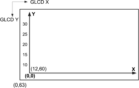
The x and y axes are drawn on the GLCD, the axes ticks are displayed, and the Y axis is labelled, as shown in Figure 12.28. The Y axis is the temperature, and the X axis is the time where every pixel corresponds to 1 second in real-time.
Figure 12.28 Layout of the screen
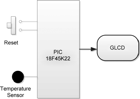
12.5.2 Block Diagram
The block diagram of the project is shown in Figure 12.29.
Figure 12.29 Block diagram of the project
12.5.3 Circuit Diagram
The circuit diagram of the project is as shown in Figure 12.30. The LM35DZ temperature sensor is connected to analogue port RA0 (or AN0) of the microcontroller. This is a 3-pin analogue temperature sensor integrated circuit. Two of the pins are connected to +5 V and ground, where the third pin is the output. This sensor provides an output voltage directly proportional to the measured temperature. The output of the sensor is given by
(12.2) ![]()
Get Using LEDs, LCDs and GLCDs in Microcontroller Projects now with the O’Reilly learning platform.
O’Reilly members experience books, live events, courses curated by job role, and more from O’Reilly and nearly 200 top publishers.

