12.3 PROJECT 12.3 – GLCD Dice
12.3.1 Project Description
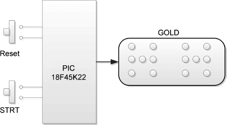
In this project we design a GLCD based dice. The shapes of the numbers on two dices are imitated on a GLCD. The user presses a STRT button to ‘throw’ two dices. The dice numbers are then displayed for 5 seconds on the GLCD as real dice faces. After this time, the screen goes blank and the user is ready to ‘throw’ two new dices.
12.3.2 Block Diagram
The block diagram of the project is shown in Figure 12.14.
Figure 12.14 Block diagram of the project
12.3.3 Circuit Diagram
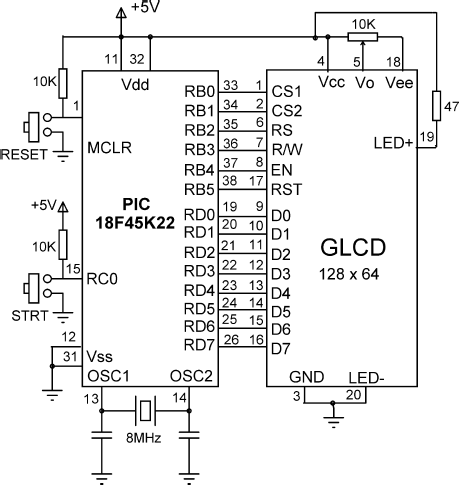
The circuit diagram of the project is shown in Figure 12.15. The GLCD is connected to PORT B and PORT D of the microcontroller. The STRT button is normally at logic 1 and is connected to port pin RC0 of the microcontroller. When the button is pressed, RC0 goes to logic 0.
Figure 12.15 Circuit diagram of the project
12.3.4 Project PDL
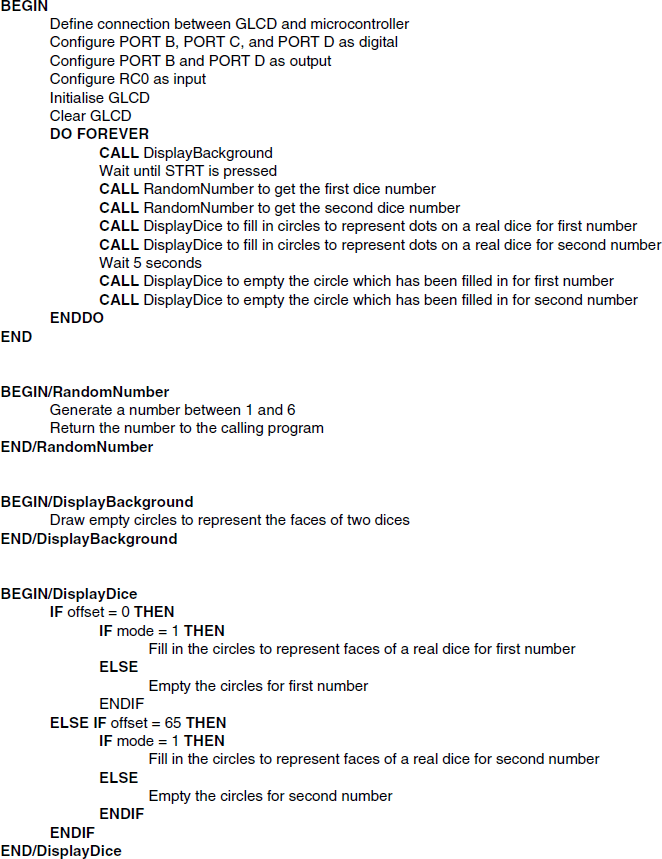
The PDL of this project is given in Figure 12.16.
Figure 12.16 PDL of the project
12.3.5 Project Program
The screen layout of the two dice shapes are designed using the Windows Paint program. Circles are used to represent the dots on a real dice. A dice number is shown by filling these circles to correspond to the dots on the ...
Get Using LEDs, LCDs and GLCDs in Microcontroller Projects now with the O’Reilly learning platform.
O’Reilly members experience books, live events, courses curated by job role, and more from O’Reilly and nearly 200 top publishers.

