Variations on Deployment Diagrams
Most of the time deployment diagrams are used for their intended purpose: to show how an application is physically deployed. Some modelers prefer to display the bare minimum, just showing how many machines they will need and how they are supposed to talk. Modelers often take liberties with the official notation and will specify minimum requirements for their machines, as in Figure 6-18.
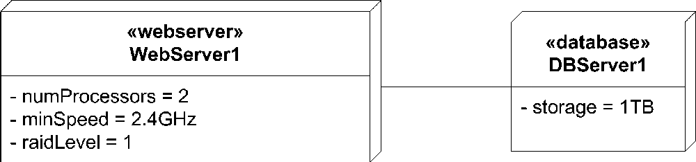
Figure 6-18. A minimal deployment diagram
Obviously Figure 6-18 doesn't provide any information on actual software deployment. Instead of focusing on the node's configuration, you can focus on the software deployment configuration and specify details for executing your software, as shown in Figure 6-19.
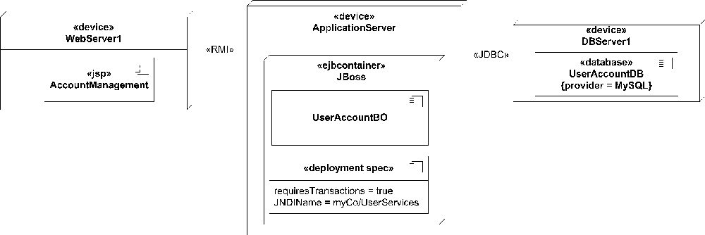
Figure 6-19. Detailed application deployment diagram
For the sake of completeness, we should mention that deployment diagrams have been used to show network configurations. Properties and tagged values can be used to show network configuration options rather than machine hardware details. Figure 6-20 shows an example network modeled as a deployment diagram. Be warned, though: deployment diagrams were not designed with network modeling in mind, so a professional network administrator may find the syntax lacking.
Figure 6-20. A sample network topology using a deployment ...
Get UML 2.0 in a Nutshell now with the O’Reilly learning platform.
O’Reilly members experience books, live events, courses curated by job role, and more from O’Reilly and nearly 200 top publishers.

