T1 Circuit Timing
CSU/DSUs are like bridges. They have one interface in telco territory and one interface in data-communications territory. Both are serial interfaces that make use of tight timing tolerances. Appropriate configuration of the CSU/DSU to work within the timing straitjacket is essential.
Receive Clock Inference on the Network Interface
In the T1 world, clock signals are not transmitted separately from the data stream. Instead, receivers must extract the clock from the data signal based on the stream itself. Each bit time slot is 648 nanoseconds. Pulses are transmitted with a 50% duty cycle, meaning that for the middle half of the time slot, the voltage is at its peak. Based on these characteristics, the receiving CSU/DSU infers time slot boundaries from incoming pulses. Ideally, each pulse comes in the middle of a time slot, so finding time-slot boundaries is simply a matter of going 324 ns in each direction. Figure 5-3 illustrates clock inference from pulse reception.
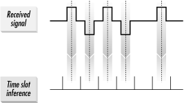
Figure 5-3. T1 clock inference from pulse reception
In practice, of course, things are never quite as simple, and CSU/DSUs must compensate for a variety of non-ideal conditions. Clock signals may exhibit both short-term and long-term irregularities in their timing intervals. Short-term deviation is called jitter, and long-term deviation is referred to as wander.
Tip
Timing on the T1 network ...
Get T1: A Survival Guide now with the O’Reilly learning platform.
O’Reilly members experience books, live events, courses curated by job role, and more from O’Reilly and nearly 200 top publishers.

