In the beginning, T1s were deployed to users as high-capacity voice trunks and were terminated by devices called channel banks. Western Electric called the first channel bank, which was first placed in service in 1962, the D1. Later channel banks received successively higher numbers: the D2 channel bank was introduced in 1969, the D3 was completed in 1972, and the D4 made its debut in 1976. Each new product introduced new features. With the D2 channel bank, Western Electric introduced the superframe (SF) standard. Some manuals may refer to the SF format as the D4 format, which is somewhat erroneous—the D2 channel bank was sold in the late 1960s, long before the D4 channel bank became commonplace nearly twenty years later. Superframe formatting groups 12 channels together into a single structure called a superframe, as shown in Figure 4-2.
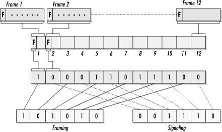
24 DS0 channels are bundled into frames. Twelve frames are then put together to form one superframe. The framing bits from the 12 constituent frames form a frame bit sequence, which is always 100011011100, as Figure 4-2 shows. Odd bit positions in the superframe are terminal framing bits, abbreviated Ft(101010), and even bit positions are signaling framing bits, abbreviated Fs(001110).
AT&T’s introduction of the D2 channel bank brought link monitoring into existence—a major step forward. Alarm signals indicated severe error conditions. Table 4-2 summarizes the alarm conditions available on superframe links. Alarms initially had color names because of the corresponding color of the indicator lights on channel banks.
Table 4-2. Superframe alarm conditions
|
Name |
Cause |
|---|---|
|
Red alarmReceive alarm |
This is declared when the local CSU/DSU is not able to detect an incoming framing signal. |
|
Yellow alarm[a]Remote alarm |
This is sent as the outbound signal when a CSU/DSU enters the red alarm state to inform the remote end of a potential failure. The most important thing about the yellow alarm is that, in most cases, the span from the remote end to the local end must be functional to send the yellow alarm signal. On SF-framed links, a yellow alarm is indicated by setting the second bit of each channel to zero. |
|
Blue alarmAlarm indication signal (AIS) |
When no incoming signal is detected, a CSU/DSU transmits an unframed all-ones pattern. AIS signals serve two purposes: the continuous transitions may help resynchronize the network, and they indicate a problem to the network. |
[a] Some equipment may refer to the yellow alarm as the remote alarm indicator (RAI), which is the ITU name for a yellow alarm. | |
Get T1: A Survival Guide now with the O’Reilly learning platform.
O’Reilly members experience books, live events, courses curated by job role, and more from O’Reilly and nearly 200 top publishers.

