16.7 DIVIDER
A basic divider deduced from algorithm 16.6 is shown in Figure 16.9. The inputs of the (p + 1)-digit divider are s1/B and s2 (Comment 6.1), so that the dividend is smaller than the divisor. The precision is chosen equal to p + 3 digits. Thus (see Section 6.1) the outputs quotient and remainder satisfy the relation
![]()
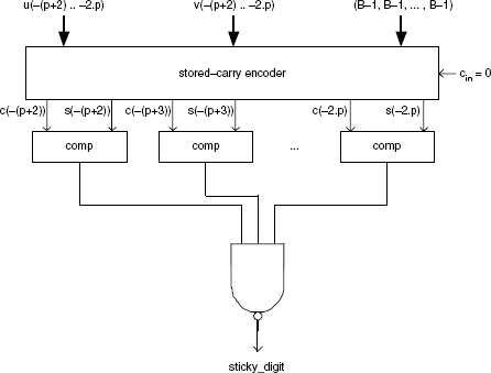
Figure 16.8 Sticky digit generation.
that is,
![]()
The sticky digit is equal to 1 if r > 0 and to 0 if r = 0. The final approximation of the exact result is
![]()
Example 16.9 (Complete VHDL code available.) Generate the VHDL model of a generic floating-point divider. It is made up of three blocks:
1. Division. This block includes the (p + 2)-digit divider, the subtractor, the xor gate, and the sticky digit generation circuit. Any type of divider can be used (Chapter 13). In this model a modified (dividend = s1/B) restoring divider has been used:
entity division is port ( s1, s2: in digit_vector(0 downto -p); signl, sign2: in std_logic; e1, e2: in integer; s: out digit_vector(0 downto -(p+3)); sign: out std_logic; e: out integer ); end division; architecture circuit of ...
Get Synthesis of Arithmetic Circuits: FPGA, ASIC and Embedded Systems now with the O’Reilly learning platform.
O’Reilly members experience books, live events, courses curated by job role, and more from O’Reilly and nearly 200 top publishers.

