10.4 Modes of a Planar Waveguide
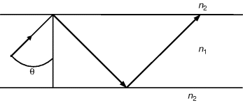
The simplest optical waveguide is a planar waveguide, shown in Figure 10.2. We modify the structure slightly to consider a more general structure, in which the refractive indices of the upper and lower cladding layers are different and are, respectively, n3 and n2 as shown in left of Figure 10.3. The Cartesian coordinate system used to define the geometry is also shown.
Figure 10.2 Ray path showing total internal reflection and guidance of mode in a symmetric slab waveguide.

Figure 10.3 (Left) Ray path and propagation in planar waveguide; and (right) propagation constants in y- and z-directions.

The thickness of the guide layer along the y direction along which the light is confined is a and the direction of propagation of the electromagnetic wave is z. The zigzag path denotes the direction of wave normal as the waves propagate through the waveguide with wave vector k (= k0n1), where k0 is the free space wave vector (k0 = 2π/λ0, where λ0 is the free space wavelength). The components of k along the y- and z-directions are
The relation between the propagation constants and the wave normal is shown in Figure 10.3 (right).
As the light is guided ...
Get Silicon Photonics: Fundamentals and Devices now with the O’Reilly learning platform.
O’Reilly members experience books, live events, courses curated by job role, and more from O’Reilly and nearly 200 top publishers.

