14.5 Logic Gates
Logic gates are used to connect events. The two fundamental gates are the AND and OR gates. Table 14.2 describes the gate functions and also provides insight to their applicability.
Table 14.2 Logic Gates
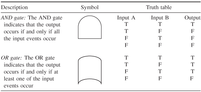
Electrical circuits are used to illustrate the use of AND and OR gates. Figure 14.1 is a picture of switches in series and the corresponding fault tree. In order for the bulb to be lit, all the switches must be in the closed position. The logic gate is an AND gate.
Figure 14.1 Switches representing AND gates.
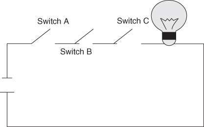
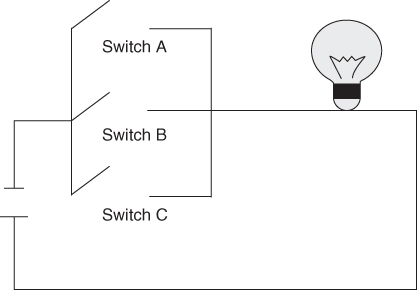
Figure 14.2 represents the OR gate logic. The bulb will be lit if any of the switches are closed.
Figure 14.2 Switches representing OR gates.
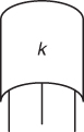
Other gates that can be used in more complicated trees are shown in Table 14.3. These logic gates are used when representing complex systems. Other gates can be used as well. These are usually very specialized in nature and do not have widespread application.
Table 14.3 More Complicated Logic Gates
| Symbol name | Symbol | Description |
| Voting OR (k-out-of-n) |
|
The output event occurs if k or more of the input events ... |
Get Risk Assessment: Tools, Techniques, and Their Applications now with the O’Reilly learning platform.
O’Reilly members experience books, live events, courses curated by job role, and more from O’Reilly and nearly 200 top publishers.

