6.11 Balanced-to-Unbalanced Circuits
In Section 4.9 we discussed balanced and unbalanced transmission lines. Microstrip lines, striplines and coaxial lines are unbalanced transmission lines. Symmetrical two-wire lines and coupled microstrip lines represent balanced transmission lines. A balanced line is commonly driven with symmetrical signals where the voltages at the terminals have equal magnitude but opposite signs with respect to ground U1 = − U2 (see Equation 4.75).
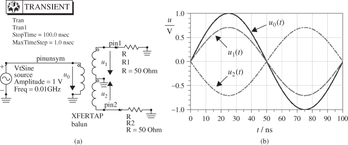
If we connect a balanced transmission line or component to an unbalanced transmission line or component baluns (balanced-to-unbalanced transformers) are used. For low and medium frequencies a transformer with a secondary centre tap provides a broadband conversion between unbalanced and balanced systems (Figure 6.43a). Such a transformer can additionally be used for impedance matching. Figure 6.43b shows an unbalanced input signal u0(t) and balanced output signals u1(t) and u2(t) where u1(t) = − u2(t).
Figure 6.43 Balanced-to-unbalanced circuit (balun) with transformer.
At higher frequencies transformers become unattractive due to increased losses. Therefore, transmission line structures are commonly used to provide narrowband conversion. Figure 6.44a shows a balun with two λ/4-lines to provide a 180° phase shift. The unbalanced signal on a microstrip line is matched to a power divider and split into two signals ...
Get RF and Microwave Engineering: Fundamentals of Wireless Communications now with the O’Reilly learning platform.
O’Reilly members experience books, live events, courses curated by job role, and more from O’Reilly and nearly 200 top publishers.

