3.5 Transmitter Impairments Simulation
3.5.1 Introduction
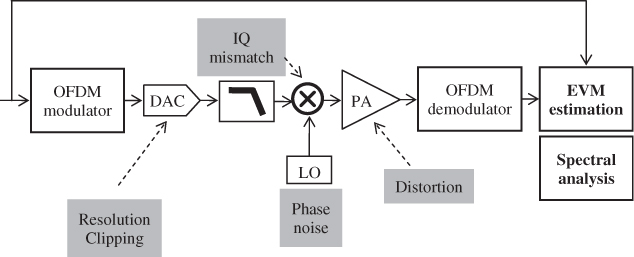
Figure 3.9 shows the configuration of the transmitter analog front-end simulator, including the following impairments modeling:
- DAC quantization and clipping;
- quadrature mixer IQ mismatch (phase and amplitude);
- LO phase noise ;
- PA distortion.
Figure 3.9 Transmitter analog front-end impairments simulated bench
The DAC is clocked at four times the IFFT/FFT sampling frequency, that is, 80 MHz for WiFi and 89.6 MHz for WiMAX, for distortion modeling and out-of-band emission measurements. We will study each of these impairments separately in order to isolate their impact on the transmitter performance; the aim is to obtain EVM curves as a function of the impairments, which allows us to easily identify the system performance bottlenecks.
For the OFDM signal demodulation, the time synchronization is ideal, meaning that the FFT is perfectly aligned with the received symbols. In addition, a channel estimation is done using the pilots present in both WiFi and WiMAX OFDM symbols in order to track and compensate the phase rotation of the constellation symbol per symbol, especially due to the phase noise, before the subcarrier demapping and the EVM estimation.
3.5.2 DAC Clipping and Resolution
Because WiFi and mobile WiMAX signals exhibit an equivalent Gaussian distribution in the time domain, illustrated in Figure 3.7 by their similar ...
Get RF Analog Impairments Modeling for Communication Systems Simulation: Application to OFDM-based Transceivers now with the O’Reilly learning platform.
O’Reilly members experience books, live events, courses curated by job role, and more from O’Reilly and nearly 200 top publishers.

