2.9 IP2 and IP3: Second- and Third-Order Nonlinearities
2.9.1 Harmonics (Single-Tone Test)
If a monochromatic signal is fed into a nonlinear system, the output is composed of the input frequency (fundamental) and harmonics that are integer multiples of the fundamental frequency, as depicted in Figure 2.48. By only considering second- and third-order nonlinearities of the system, the output of a nonlinear block can be modeled as a simple polynomial function:
where α1 is the small-signal gain and α2 and α3 are positive factors related to the second- and third-order nonlinearities, respectively.
Figure 2.48 Input and output (frequency domain) of a nonlinear system (single-tone test)
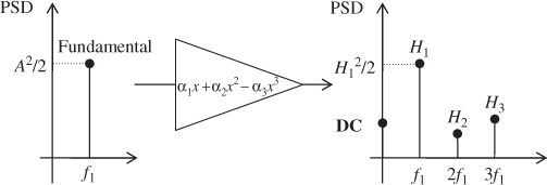
The negative term in front of α3 is due to the fact that the third-order term compresses the gain of the fundamental and to avoid any confusion arising from the assumption α3 < 0.
If x(t) = A cos(ω1t), we can develop Equation 2.152:
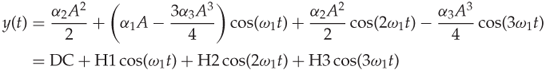
in which we find a DC component, the input frequency called the fundamental with amplitude H1, and the second- and third-order terms called the “harmonics” with amplitudes H2 and H3, respectively.
As the input signal amplitude increases, the output level of the fundamental ...
Get RF Analog Impairments Modeling for Communication Systems Simulation: Application to OFDM-based Transceivers now with the O’Reilly learning platform.
O’Reilly members experience books, live events, courses curated by job role, and more from O’Reilly and nearly 200 top publishers.

