2.1 Introduction
Modern on-chip wireless transceivers usually use zero-IF, also called direct conversion or low-IF architectures because both are well suited to system integration by avoiding the use of external RF filters as are seen in the superheterodyne case.
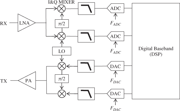
Figure 2.1 presents a simple schematic overview of zero-IF and low-IF AFE architectures. The RF analog receiver is composed of a LNA fixing its sensitivity, a LO and a quadrature mixer for frequency down-converting the signal around DC (zero-IF) or in low-IF, and finally anti-alias filtering and ADC for sampling and digitizing the baseband signal. The RF analog transmitter is composed of a DAC with reconstruction filtering for converting the baseband digital signal into analog, a LO and a quadrature mixer for frequency up-converting the signal to RF, and finally a PA for delivering the required transmit power.
Figure 2.1 Zero-IF or low-IF transceiver architecture
In this chapter we will especially focus on the principal impairments present in the RF AFE:
- thermal and flicker noises;
- LO phase noise;
- sampling jitter;
- carrier frequency offset (CFO) and sampling frequency offset (SFO);
- DAC and ADC quantization noise and clipping;
- quadrature imbalance;
- second-order intercept point (IP2)/third-order intercept point (IP3) nonlinearities and PA distortions.
From the description of these imperfections we derive mathematical models ...
Get RF Analog Impairments Modeling for Communication Systems Simulation: Application to OFDM-based Transceivers now with the O’Reilly learning platform.
O’Reilly members experience books, live events, courses curated by job role, and more from O’Reilly and nearly 200 top publishers.

