16.3 555 TIMER APPLICATIONS
The 555 timer is another linear IC. The functional block diagram of a 555 timer is given in Fig. 16.13(a) and the pin diagram of a 555 timer is shown in Fig. 16.13(b). A 555 timer consists of:
- A potential divider network comprising R1, R2 and R3
- Two voltage comparators
- An R–S flip-flop
- An inverting buffer output stage
- Two transistors, Q1 and Q2
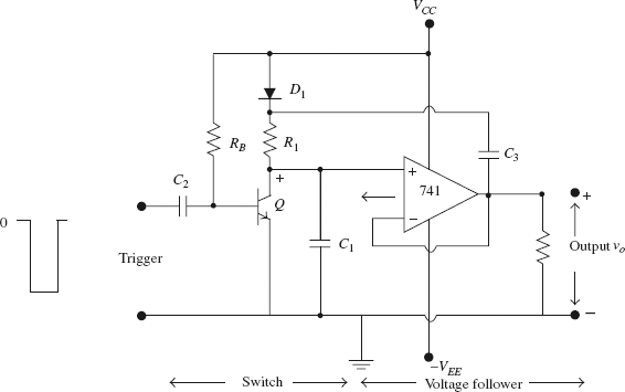
FIGURE 16.12(b) A bootstrap sweep generator using an op-amp voltage follower
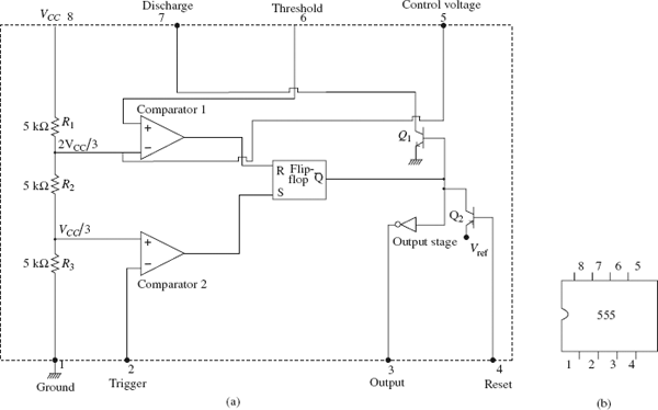
FIGURE 16.13(a) The functional block diagram of a 555 timer; and (b) The pin diagram of a 555 ...
Get Pulse and Digital Circuits now with the O’Reilly learning platform.
O’Reilly members experience books, live events, courses curated by job role, and more from O’Reilly and nearly 200 top publishers.

