6.5 Predictive Control of an AC–DC–AC Converter
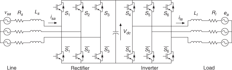
This section presents a control scheme for a regenerative AC–DC–AC converter using model predictive control. The power circuit of the converter is shown in Figure 6.13. The control strategy minimizes cost functions, which represent the desired behavior of the converter. At the inverter side, the load current error is minimized, while at the input side, the active power and reactive power are directly controlled.
Figure 6.13 AC–DC–AC converter model (Rodriguez et al., 2005 © IEEE)
In an AC–DC–AC converter it is possible to consider the inverter variables in the rectifier control scheme to improve the input–output power matching and reduce the fluctuations of the DC link voltage. This idea has been studied using output power feedforward in [4], a feedback linearization method in [9], and a master–slave method in [10]. The use of predictive control for this converter was proposed in [11].
6.5.1 Control of the Inverter Side
The control of the inverter side is similar to the scheme presented in Chapter 4. The effect of each possible voltage vector generated by the inverter on the behavior of the load current is predicted using the load model. Then, each prediction is evaluated using a cost function ginv. The voltage vector that minimizes this function is selected and applied during the next sampling period. The cost function to be minimized ...
Get Predictive Control of Power Converters and Electrical Drives now with the O’Reilly learning platform.
O’Reilly members experience books, live events, courses curated by job role, and more from O’Reilly and nearly 200 top publishers.

