6.1 Introduction
Rectifiers are by far the most widely used converters in power electronics. The transformation from alternating current to direct current performed by rectifiers is used in a large variety of applications and from small power up to several megawatts.
The diode rectifier shown in Figure 6.1a is the simplest topology, which produces a fixed DC voltage, while the diodes are commutated by the AC voltages. This circuit is also known as a line-commutated rectifier and the power semiconductors operate at very low switching frequency. The main advantages of the diode rectifier are its simplicity and extremely low cost. The disadvantages and limitations of the three-phase diode rectifier are:
Figure 6.1 Three-phase rectifier. (a) Diode rectifier. (b) Thyristor rectifier. (c) AFE rectifier
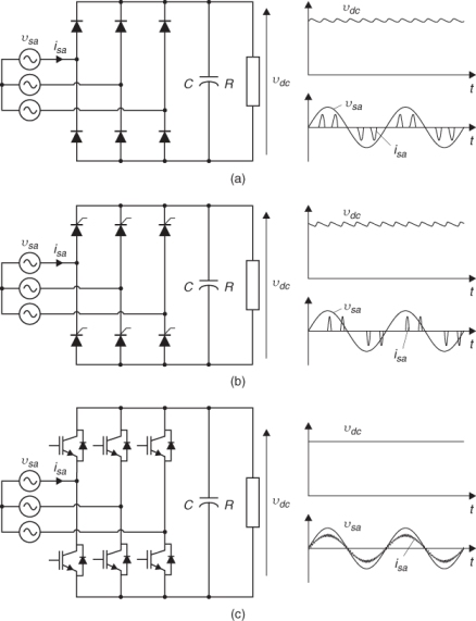
The second topology of importance is the thyristor rectifier, presented in Figure 6.1b, which introduces the possibility of control of power flow by changing the angle of the gate pulses (α) for the thyristors. Through this angle α it is possible to change the mean value of the load voltage, ...
Get Predictive Control of Power Converters and Electrical Drives now with the O’Reilly learning platform.
O’Reilly members experience books, live events, courses curated by job role, and more from O’Reilly and nearly 200 top publishers.

