5.2 System Model
The power circuit of the NPC inverter is shown in Figure 5.1. Each phase of the inverter is composed of four switches and two diodes where the two center switches and the diodes allow the output terminal to be connected to the neutral point of the DC link. This configuration allows the generation of three voltage levels at the output terminal of phase x, with respect to the neutral point 0, considering the switching combinations given in Table 5.1.
Figure 5.1 Circuit of a three-phase NPC inverter connected to a resistive–inductive–active load (Vargas et al., 2007 © IEEE)
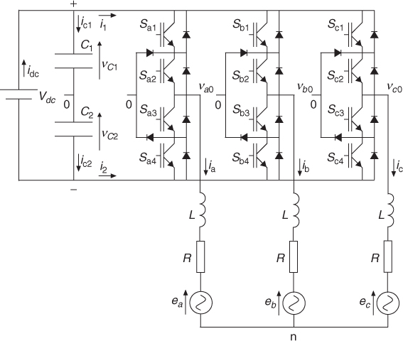
Table 5.1 Switching states for one phase of the inverter
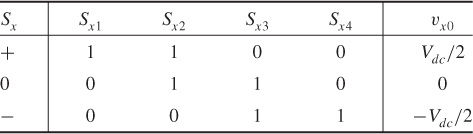
Switching state variable Sx represents the switching state of phase x, with x = {a, b, c}, and it has three possible values denoted by + , 0, and − that represent the switching combinations that generate Vdc/2, 0, and − Vdc/2, respectively, at the output of the inverter phase.
For the three phases of the inverter, 27 switching states are generated, which produce 19 different voltage vectors, as shown in Figure 5.2. Note that some switching states are redundant, generating the same voltage vector. For example, vector V0 can be generated by three different switching states: ( + , + , + ), (0, 0, 0), and ( − , − , − ), which generate the load ...
Get Predictive Control of Power Converters and Electrical Drives now with the O’Reilly learning platform.
O’Reilly members experience books, live events, courses curated by job role, and more from O’Reilly and nearly 200 top publishers.

