State Diagram
We’ve had a number of different engineers working on VOCAL and the protocol stacks. Some have been up-to-date with cutting-edge (and sometimes bleeding-edge) tools and technology, while others have come to us with a more traditional approach to programming. The MGCP translator was developed using a traditional programming approach, and it differs from other VOCAL components both in its C code base and the fact that it has been written with functional rather than object-oriented code.
In line with standard engineering projects, a judgment call was made to strike a balance between designing an enormous state machine that was impossible to manage and a small, cryptic machine that was impossible to understand. While most of the processes pertain to single state/event combinations, some have been reused for similar situations. The state diagram shown in Figure 15-5, rather than being a picture full of boxes and arrows, is a table that describes the behavior of each state during different events. The key to this table follows the diagram, which is followed by descriptions of two call flows as they work their way through the state machine. These descriptions are illustrated in Figures 15-6 and 15-7.
Key to the State Diagram
The symbols and abbreviations used in the state diagram are described in the following sections.
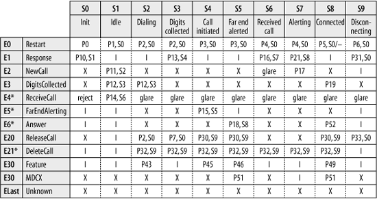
Figure 15-5. MGCP translator state machine diagram
General
Get Practical VoIP Using VOCAL now with the O’Reilly learning platform.
O’Reilly members experience books, live events, courses curated by job role, and more from O’Reilly and nearly 200 top publishers.

