DB25 pin definitions
EIA-232D defines pin assignments, but does not specify physical connectors. In the PC environment at least, a well-established de facto standard does exist for 25-pin serial connections. By convention, DTE devices (e.g., PC serial ports) use a 25-pin male D-sub plug connector, designated DB25M. DCE devices (e.g., modems) use a 25-hole DB25F female socket connector. There are exceptions. For example, some serial printers are DTE devices but use a DB25F connector. Figure 22-1 shows a DB25 connector.
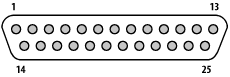
Figure 22-1. A DB9 connector
Table 22-1 lists DB25 pin assignments. The column headings are self-explanatory, except the following:
- I/O
Signal direction, relative to the DTE. For example, a DCE (modem) asserts voltage onPin 5 (CTS) to notify the DTE (serial port) that it is ready to accept data from the serial port. We list this signal direction (from the DCE to the DTE) as In. Pins 1 and 7 are ground pins, and have no signal direction. Pin 11 is unassigned, and so has no signal direction.
- CCITT, EIA, and RS
The circuit numbers/names used by CCITT, EIA, and RS standards documents, respectively. Circuits with a hyphen (-) are defined by the standard in question but not assigned a name. Circuits with a blank box are neither defined nor named.
Table 22-1. DB25 serial port pin assignments
|
Pin |
I/O |
CCITT |
EIA |
RS |
Common name(s) |
Abbreviations |
|---|---|---|---|---|---|---|
|
1 |
- |
101 |
- |
AA |
Chassis Ground ... |
Get PC Hardware in a Nutshell, 3rd Edition now with the O’Reilly learning platform.
O’Reilly members experience books, live events, courses curated by job role, and more from O’Reilly and nearly 200 top publishers.

