AT Keyboard Interface
The AT keyboard interface was introduced with the IBM PC/AT in 1984, and is still used by the few AT and BAT motherboards still being produced. AT keyboards use the 5-pin DIN connector (female at the PC), shown in Figure 19-1 and whose pinouts are described in Table 19-1. On the PC side, the AT keyboard uses an Intel 8042 or equivalent interface chip, which is assigned IRQ1 and I/O base address 0060.
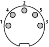
Figure 19-1. The AT keyboard connector
Table 19-1. AT keyboard interface signals and pinout
|
Pin |
Signal name |
Description |
|---|---|---|
|
1 |
CLOCK |
Keyboard clock; open collector CLK, CTS |
|
2 |
DATA |
Keyboard data; open collector RxD/TxD, RTS |
|
3 |
RESERVED |
Reset (usually not connected) |
|
4 |
GROUND |
Signal ground |
|
5 |
VCC |
+5VDC |
The pin descriptions are self-explanatory, other than Pin 3. The 83-key IBM PC/XT keyboard and some 84-key IBM PC/AT keyboards used an early keyboard protocol that did not include a software reset command. For these keyboards, the PC uses Pin 3 to send a hardware reset to the keyboard. All systems and keyboards made in the last 15 years use a keyboard protocol that includes a software reset command, and nearly all recent keyboards leave Pin 3 unconnected.
Get PC Hardware in a Nutshell, 3rd Edition now with the O’Reilly learning platform.
O’Reilly members experience books, live events, courses curated by job role, and more from O’Reilly and nearly 200 top publishers.

