10Multielectrode Systems
10.1 Multielectrode Structures
(Note: This chapter discusses applications, mostly circuital, of the structural models developed in Chapters 8 and 9. There is virtually nothing new in the computer code. Consequently, computer source listings are not included; only unique programming issues (if any) will be discussed. All capacitance values presented will be calculated as described in Chapter 9 — specifically, calculating the capacitance for several resolutions and then extrapolating the results to a hypothetical infinite resolution limit. There is no need for numerical analyses in this chapter's materials, so, formally, this chapter is outside the scope of this book. The materials of this chapter, however, are such a logical extension and typical application of the results of the previous chapters that including them seems reasonable and justified.
Figure 10.1a shows the cross section of a three-conductor transmission line. The electrodes are labeled 1 and 2 — the inner conductors, and 3 — the outer (enclosing) box.
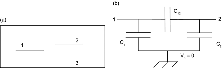
FIGURE 10.1 Three-conductor structure (a) and its circuital equivalent (b).
Figure 10.1b shows an equivalent circuit of this structure. A circuit notation that has not been used previously is introduced in this figure. In this example, electrode 3 (the enclosing box) will always be fixed at zero volts. This is indicated by the “ground” symbol at ...
Get Introduction to Numerical Electrostatics Using MATLAB now with the O’Reilly learning platform.
O’Reilly members experience books, live events, courses curated by job role, and more from O’Reilly and nearly 200 top publishers.

