9.8 SEQUENTIAL SERIAL ADDER
Sequential serial adders are economically efficient and simple to build. A serial adder consists of a 1-bit full-adder and several shift registers. In serial adders, pairs of bits are added simultaneously during each clock cycle. Two right-shift registers are used to hold the numbers (A and B) to be added, while one left-shift register is used to hold the sum (S). A block diagram of a serial adder is shown in Figure 9.32.
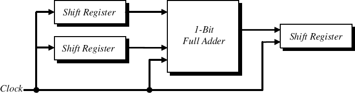
Figure 9.32 Block Diagram of a Serial Adder
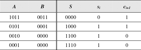
Figure 9.33 Time Sequence of the Operation of a 4-bit Serial Adder
A finite-state machine adder performs the addition operation on the values stored in the input shift registers and stores the sum in a separate shift register during several clockcycles. During each clock cycle, two input bits ai and bi are shifted from the two input right-shift registers into the 1-bit full-adder, which adds the two bits and evaluates the sum bit si and the carryout bit ci+1. The sum bit si, is shifted out to the left-shift register and the carryout bit ci+1 is stored in the state memory of the serial adder for the next two bits. The time sequence of the operation of a 4-bit serial adder is illustrated in Figure 9.33.
The state memory of a serial adder can only hold a bit for the carryout from a single 2-bit ...
Get Introduction to Digital Systems: Modeling, Synthesis, and Simulation Using VHDL now with the O’Reilly learning platform.
O’Reilly members experience books, live events, courses curated by job role, and more from O’Reilly and nearly 200 top publishers.

