8.4 FLIP-FLOPS
Flip-flops are synchronous bistable storage devices capable of storing one bit. The term synchronous means that the output state changes only at a specified point on a triggering input called the clock signal. That is, the output changes are synchronized with the clock signal. A basic flip-flop consists of two parts: a primary latch (master) and a secondary latch (slave). A flip-flop is also known as a two-section flip-flop. The input latch is operating as the master section and the output latch is slaved to the master during half of each clock cycle. We use the terms primary and secondary instead of master and slave.
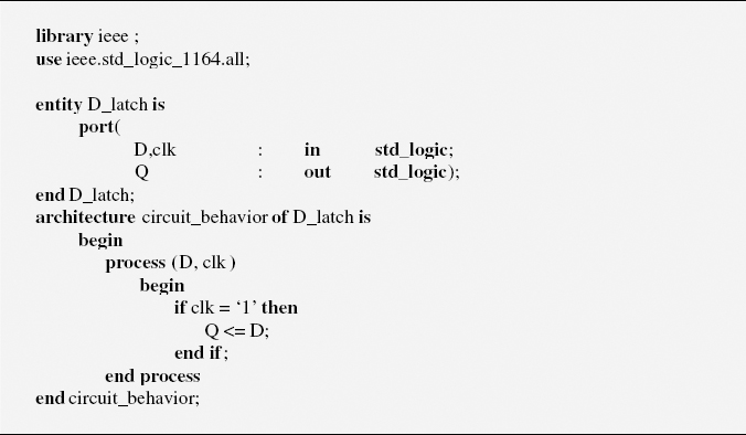
Figure 8.13 VHDL Code Implementation of a Gated D Latch
8.4.1 SR Flip-Flop
An SR flip-flop consists of two identical gated SR latches. However, the inverter connected between the two Clk inputs ensures that the two sections will be enabled during opposite half-cycles of the clock signal. This is the key to the operation of this flip-flop circuit. Outputs Q and ![]() of the primary SR latch are connected to the inputs of the secondary SR latch. The primary SR latch is also called master, and the secondary is called slave. The logic circuit of an SR flip-flop is illustrated in Figure 8.14.
of the primary SR latch are connected to the inputs of the secondary SR latch. The primary SR latch is also called master, and the secondary is called slave. The logic circuit of an SR flip-flop is illustrated in Figure 8.14.
The two latches use a common clock signal, but an inverter gate is connected ...
Get Introduction to Digital Systems: Modeling, Synthesis, and Simulation Using VHDL now with the O’Reilly learning platform.
O’Reilly members experience books, live events, courses curated by job role, and more from O’Reilly and nearly 200 top publishers.

