9.6 Inverter Output Filters
9.6.1 Selected Structures of Inverter Output Filters
The improvement of the AC motor operation in inverter fed drives is possible, if the shape of the stator voltage becomes as close as possible to the sinusoidal.
A motor fed by such waveforms shows higher efficiency as a result of decreasing miscellaneous losses in the machine. Motors fed by non-sinusoidal waveforms have higher eddy current losses. For high switching frequency, those losses are the dominating losses in the machine, compared to copper and hysteresis losses [14–16].
In inverter fed drives, the use of the voltage inverter output filters reduces the disturbance levels in the current and voltage waveforms.
Motor side filters may be categorized into three basic types:
1. sine filter – LC filter;
2. CM filter;
3. du/dt filter.
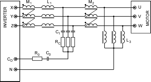
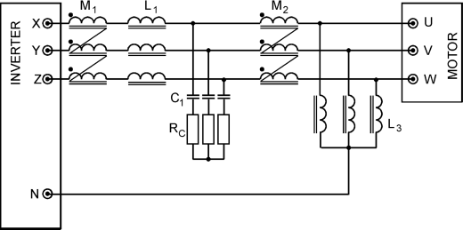
The three types of filters can be used separately or combined together in different combinations, for example, connecting a sine filter with a CM filter. In this chapter, different filters configurations are analyzed, as shown in Figures 9.24–9.30.
Figure 9.24 Inverter output filter – Structure 1

Figure 9.25 Inverter output filter – Structure 2

Figure 9.26 Inverter output filter – Structure 3
Figure 9.27 Inverter output filter – Structure 4
Figure 9.28 Inverter ...
Get High Performance Control of AC Drives with Matlab / Simulink Models now with the O’Reilly learning platform.
O’Reilly members experience books, live events, courses curated by job role, and more from O’Reilly and nearly 200 top publishers.

