Chapter 4. Drawing a Basic House
It’s time to apply the drawing techniques you’ve learned to a practical project. In this chapter, you’ll build a house with an overhanging roof and a garage. You’ll model the doors and windows and trim them out in realistic detail. To complete the project, you’ll add a driveway and a front path.
Along the way, you’ll add some new skills and techniques to your SketchUp toolkit. To start with, you’ll learn new techniques for coaxing inferences from the points, edges, and faces of your model. Equally important, you’ll learn how to lock your drawing tools so they move only along specific inferences and axes. After you’ve mastered these techniques, you’ll use them time and again. They’re one of the main reasons SketchUp artists are able to draw so quickly and accurately. You’ll also learn how to use the Offset tool to quickly model new elements—like trim details—based on the outlines of existing objects like doors and windows. So hop in your pickup truck, and drive out to the construction site. It’s time to start building.
Locking an Inference
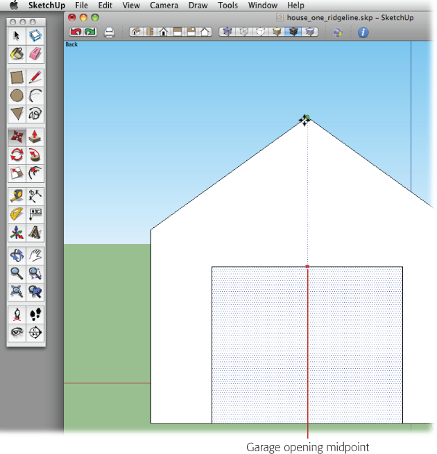
Chapter 3 introduced inferences (Finding 3-D Inferences)—handy lines that pop up from time to time to show you what SketchUp thinks you want to do. Inferences appear as temporary, dotted lines. They help you align your work to SketchUp’s main axes or find an edge’s midpoint or endpoint (Figure 4-1). You use these inferences as guides when you draw new lines and shapes. Letting SketchUp do the aligning and measuring for you makes your work go a lot faster.
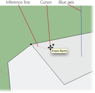
As you move a drawing tool (like the Line tool) around in 3-D space, SketchUp works behind the scenes to figure out which inference you need. When it sees a likely candidate, the program displays an inference line or highlights a particular point. Inference lines usually run from your cursor back to a point that you might find helpful. When specific points are highlighted, you see a large colorful dot under the cursor. For example, when your cursor is over an edge, a green dot indicates an endpoint, and a blue dot indicates a midpoint. Usually, accompanying tooltip messages explain the inference.
In earlier exercises when you saw an inference that you needed, you moved your cursor slowly and carefully, so you didn’t lose the inferences as you drew new shapes and lines. In this exercise, you learn how to lock an inference, so you can work more quickly instead of making your mouse tightrope walk to use the inference.
With the rectangle tool, draw a 20 x 10-foot rectangle.
Draw the rectangle on the plane formed by the red and green axes. The blue axis is perpendicular to the rectangle.
With the Push/Pull tool, pull the rectangle up into a box.
Pull the box up so it’s a good height for a one-story house—about 8 feet works well.
Click the Iso view button or choose Camera → Standard Views → Iso.
You see an angled view of the box.
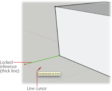
Click the box’s lower-left corner to start a line, and then move along the green axis, as shown in Figure 4-2.
When you move your cursor along the green axis, you see a thin green line. If you happen to move off the green axis, your cursor changes to a black line.
While the line is still green, press and hold Shift to lock the inference in place.
When you press Shift, the thin green line changes to a thick green line, as shown in Figure 4-2. Once you lock in the green inference, you can move your cursor all over the drawing, and no matter where you move the cursor, the line you’re drawing is locked to the green axis.
With the Shift key still down, click to finish the line.
The line is drawn parallel to the green axis. SketchUp assumes you want to continue drawing lines, so there’s a rubber band line between your cursor and the recently clicked point.
Position the cursor so that the rubber band line is aligned with the red axis.
When your line is parallel to the red axis, the rubber band line changes to a thin red line.
Press and hold Shift to lock the red inference line.
The thin red line changes to a thick red line. You can move the line cursor around your drawing to reference other points, edges, or faces.
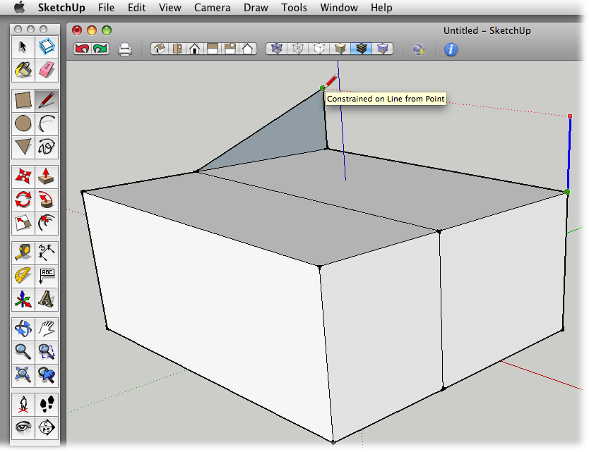
Move the line cursor to the box’s lower-right corner to reference that point.
When you move the cursor to the corner of the box, the line that you’re drawing extends along the red axis. SketchUp displays three signals when you move the cursor to the corner of the box—kind of like a basketball coach waving wildly from the sidelines:
A green dot appears at the box’s corner.
A new dotted inference line runs from the corner to the tip of the line you’re drawing.
A tooltip appears that reads, “Constrained on Line from Point.” This is SketchUp’s cryptic way of saying that you’re using the corner point as a reference for the new line.
With your cursor still referencing the corner point, click to complete the line along the red axis.
A new line appears along the red axis. This line is parallel to the bottom edge of the box, and it’s exactly the same length. Best of all, you didn’t need a carpenter’s square or a tape measure to draw it.
Draw the next line to the corner point on the box.
This line’s a cinch, and it completes a rectangle that’s attached to the box. There’s no longer a rubber band line attached to the cursor, because SketchUp knows you’ve completed the shape. Now that you’ve built out, in the next steps you’ll build up.
Click the new rectangle’s lower-left corner, and then begin to draw a line up the blue axis.
When your line is on the blue axis, the rubber band line changes to a thin blue line (see Figure 4-3).
Press and hold Shift to lock the blue inference.
The rubber band line changes to a thick blue line, and the line is locked to the blue axis.
Move the line cursor to the top edge of the box, and then click to complete the line.
You can reference any point on the top edge or face of the box to set the height of your line.
Continue by drawing a new line along the green axis back to the box.
This should only take one click, because SketchUp’s all ready for you to draw another line. When you’re done, a new face fills in.
Draw a new line along the blue axis from the right corner of your rectangle.
Use the same techniques (steps 12–14) to lock the inference and reference a point on the top of the box to set the height for your line.
Draw a horizontal line to the corner of the first box to complete the face of this new box.
After you’ve drawn the line, the face fills in.
Complete your new box by drawing a line from top corner to top corner, as shown in Figure 4-4.
Once this last line is drawn, the faces on top and to the right fill in. You’ve drawn a perfect, new box by using inferences from the first box.
Working with Sloped Surfaces
Up to now, most of the exercises have concentrated on edges and faces that are parallel and perpendicular to each other. Most of the edges and faces have been aligned with one of the three main axes: red, green, or blue. However, the world is filled with odd angles and sloped surfaces. And for good reason—a sloped surface is a great way to keep rainwater off your roof. In this section, you learn how to create sloped surfaces and how to reference an existing sloped surface to create a second sloped face at exactly the same angle.
Follow these steps to create a sloped roof for the first box you created in this chapter:
Click the corner that’s farthest to the back, and then draw a short line along the blue axis.
A new line extends above the top of the boxes. SketchUp is ready for you to draw another line.
Draw a line down to the endpoint shared by the two boxes to create a triangular shape at the front of the box.
The angle of a sloped roof begins to take shape. Use Figure 4-5 as a reference for this second line.
Repeat steps 1 and 2 to create an identical triangle on the box’s right side.
As you draw the vertical line along the blue axis, hold down the Shift key to lock the inference on the blue axis. Then move the cursor to the top of the first line as shown in Figure 4-5 to set the height for the new line.
Draw a ridgeline that connects the top point of each triangle.
Once the ridgeline is drawn, the back face and the sloped face fill in, creating the new roof.
Referencing a Sloped Surface
The first box you drew now has a handsome sloped roof. Suppose you want to create a sloped roof for the second box that continues along the same angle. You can draw this line the hard way, the inaccurate way, or the easy way. The hard way is to pull out SketchUp’s protractor tool (see Using the Protractor Tool) and to create a guideline that you use to create the new roofline. Well, that’s not too hard, but it takes unnecessary steps and clicks. The inaccurate way is to change to a side view and just try to eyeball your roofline. You can get close, but it’s unlikely you’ll draw a truly accurate line. Creating your roofline the easy way takes only two clicks and a hover. Here are the steps:
With the Line (L) tool, click the point where your two boxes meet at the top.
A rubber band line appears, attached to the end of the Line cursor on one end and to the corner point on the other.
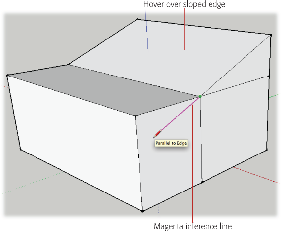
Move the cursor over the sloping line above the first box and hover along the edge.
Don’t click or do anything else; you’re just expressing your interest in the angled line. SketchUp takes note when you hover over an edge or face.
Move your cursor to extend that line across the vertical face of the second box, as shown in Figure 4-6.
When the line is at about the same slope as the roof line, it changes to a magenta color. This inference shows that the slope of the new line is identical to the line you hovered over in step 2. You can think of magenta as the parallel inference color.
Press and hold Shift to lock the inference.
The thin magenta line turns into a thick magenta line. You can move your line cursor anywhere in the window, and the line stays locked to the roof’s slope. You lock the inference to the sloped line with the Shift key, just as you locked inferences that followed the main axes.
Click the box’s right edge to finish the line.
Continue to hold Shift, and click any point along the right edge to complete the line.
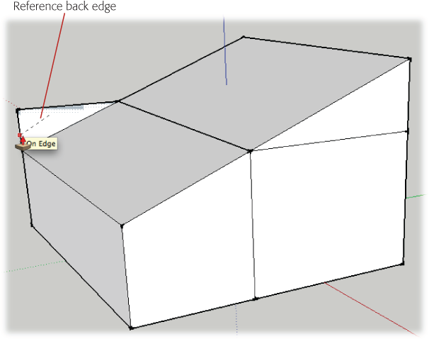
Use the Push/Pull tool to remove the portion of the box above the roofline, as shown in Figure 4-7.
Start by clicking the upper triangle, and then click on the back edge of the box to reference the back face. When you click the back face, the excess portion disappears as it’s pushed out of existence.
It was easy to match the slope of the original roofline by using the magenta inference. You’d already drawn that second box, so it was simple to determine the endpoint for your new sloped roof. But what if you wanted to create a new 3-D shape by using that same slope? Perhaps you’d like to continue this roofline all the way to the ground. SketchUp gives you an easy way to figure out the dimensions of this new addition.
Click the house’s bottom corner, and then drag a line along the green axis.
When the line is oriented to the green axis, its color changes from black to green.
Press and hold Shift to lock the green inference line.
Holding the Shift key locks the line to the green axis and changes it to a thick green line. Now you can move the Line cursor to any point in the drawing window without changing the line’s orientation.
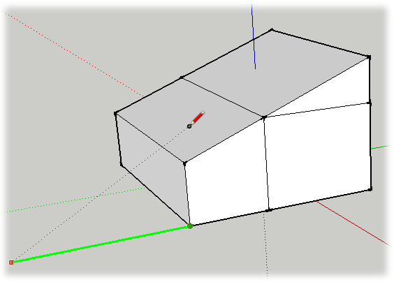
Move the Line tool to the surface of the roof and then click.
Make sure your cursor is over the face of the sloped roof (as shown in Figure 4-8). When you click, SketchUp creates a line that’s the perfect length to extend the slope of the roof to the ground.
Click the corner of the roofline to complete the new triangle.
If you want to examine the new triangle you created, use the Orbit (O) tool. Inspection shows that it’s a perfect extension of the other rooflines.
Draw a line along the red axis, using the back of the box as a reference point.
Use Shift to lock this new line to the red axis, and then click the house’s back edge to determine its length.
Draw a line to connect to the bottom of the box.
SketchUp is ready to draw a new line, so all you have to do is click the corner.
Draw a sloping line to complete the back triangle and enclose the new 3-D shape.
When you draw the last line (Figure 4-9), the top face forming the roof fills in, and the new addition is complete.

Yet Another Way to Reference a Slope
By now you’re probably confident that as long as you have a sloped edge or face to reference, you can create a matching slope for any circumstance. That’s true, but for the sake of complete disclosure, here’s one more example. If you’re following along doing the examples in SketchUp, use the Eraser tool to remove the addition you built in the last example. (For a tip on erasing several edges at once, see the box on the next page.)
In the previous example, you saw how to extend a line to just the right length to continue the slope of the roof. You can also use an inference to create a vertical line that’s just the right height to continue the roof. As shown in Figure 4-10, the method is almost exactly the same. Click to start drawing a vertical line. When the line is blue, indicating it’s aligned with the blue axis, press and hold Shift to lock in the inference. Then you can move your cursor to reference any point, edge, or face in your model. Move the cursor over the face of the sloped roof and then click; SketchUp references the slope of the roof and creates a vertical line of exactly the right height. Finish up by drawing an edge that connects the top points.
Inference Locking with the Move Tool
Inference locking works with all of the drawing tools, including those that draw lines and shapes. It also works with the tools that modify existing objects, such as the Move tool. To get a feeling for inference locking with the Move tool, start with a box like the one in Figure 4-11. Make sure the box has only six faces. If you’re using a model from the previous exercise, remove any extra shared edges.
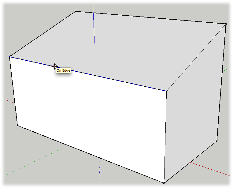
With the Move (M) tool, click the top edge of the short side of the box.
The entire edge is highlighted, and the edge moves as you move the cursor.
Move the edge up, along the blue axis.
When the edge is moving along the blue axis, you see a blue dotted line and a tooltip that says “On Blue Axis”.
Press and hold Shift to lock the movement along the blue axis.
When you press and hold Shift, the dotted line becomes thicker, and movement is constrained to the blue axis. You can move the cursor to any point in the drawing area, and the edge continues to move along the blue axis.
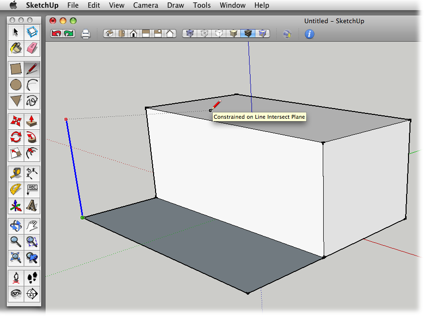
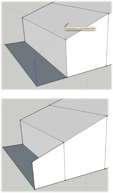
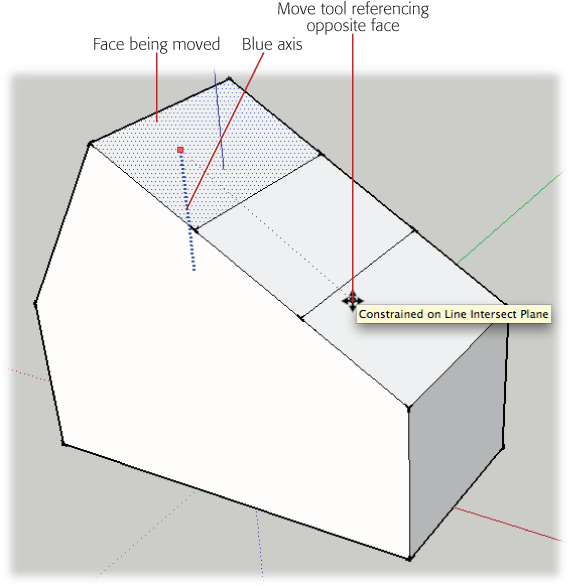
Move the cursor to the opposite edge, and click to reference the height of the opposite wall.
When your Move cursor is over the opposite edge of the box, a tooltip appears saying “Constrained on Line Intersect Plane”, as shown in Figure 4-12. This message is SketchUp’s cryptic way of telling you that you’re referencing the height of the opposite edge.

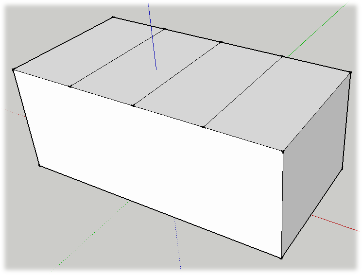
If you want to experiment some more using the Move tool, try this exercise. You can use the box from the previous exercise, or create a new box similar to the one in Figure 4-13. Find the midpoint along one of the long edges, and draw a line from midpoint to midpoint, dividing the top of the box into two halves. Doing that divides the long edges into two parts, where each part has its own midpoint. Divide the two parts again, so that the top of your box looks like Figure 4-13.
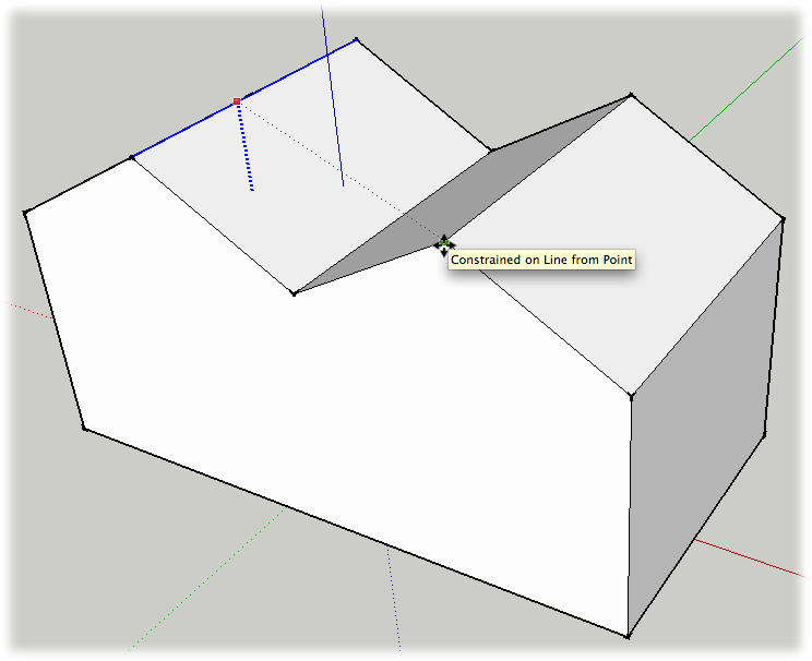
Use the Move (M) tool to pull up one of the lines to create a peaked roofline. When the movement is along the blue axis, you see a blue dotted line and a tooltip message that says “On Blue Axis”. Press and hold Shift to lock the movement to that axis. Click to complete the movement and the reshaping of the roofline. Next click one of the other lines in the roof, as shown in Figure 4-14. Pull it up in the same manner, locking it to the blue axis. Then move your cursor over to the first ridgeline and click. This creates two roof ridges of exactly the same height.
You can use inference locking as you move an entire face and all its edges. For example, click one of the middle roof faces. Begin to move the face along the blue axis, and lock the inference by holding Shift. Once the inference is locked, reference the opposite sloping face, as shown in Figure 4-15. Click the face, and you create a tall roof with a single, off-center ridgeline.
Using Inference Locking with Shape Tools
If you’ve followed all the exercises in this chapter, you’re probably a pro at locking inferences and referencing points, edges, and faces in your model. All that practice will come in handy as you work in SketchUp. This last example shows you how you can use references from one object, such as a house, to align shapes and faces that are completely unattached to that object. Again, this power comes from a combination of inference locking and SketchUp’s click-move-click drawing method.
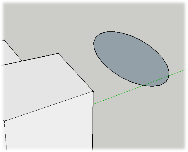
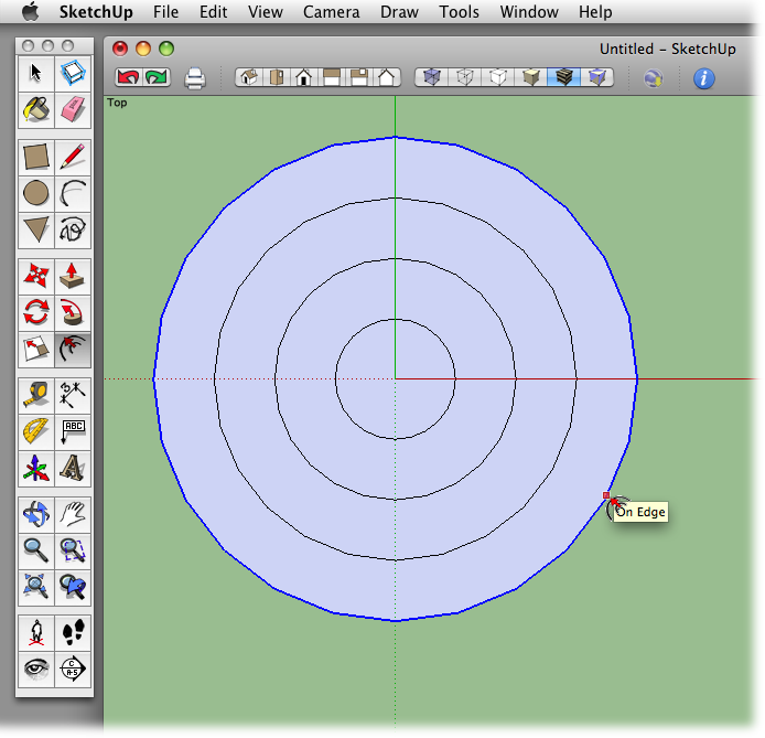
Start with a model that has a couple of sloped surfaces, like the house model from the previous exercises. Select one of the shape tools, like the Circle or Polygon tool. Notice that when you hold the shape tool over one of the surfaces of the house, the tool automatically orients itself to the surface underneath. Move to a different surface, and the tool snaps to that orientation. Move the tool to one of the sloped roof surfaces, and then press and hold Shift. Move the tool away from that surface, and then click-move-click to draw the shape in mid-air, away from the house model. When you’re done, it should look something like Figure 4-16. The shape should be oriented to the same slope as the roof. Use the Orbit (O) tool to maneuver around and see the shape from different angles. If you want some more practice, draw shapes with the Rectangle and Polygon tools that are aligned to some of the other surfaces of the house.
Making Doors and Windows
When you’re building a house in the real world, you spend a lot of time measuring and aligning the different elements. You may want to align several windows so they’re at the same height. Perhaps you’d like to position a garage door so it’s perfectly centered underneath the eaves. In the real world, that takes a lot of quality time with your tape measure. In SketchUp you can take advantage of computer-assisted shortcuts, most importantly, that old friend the inference.
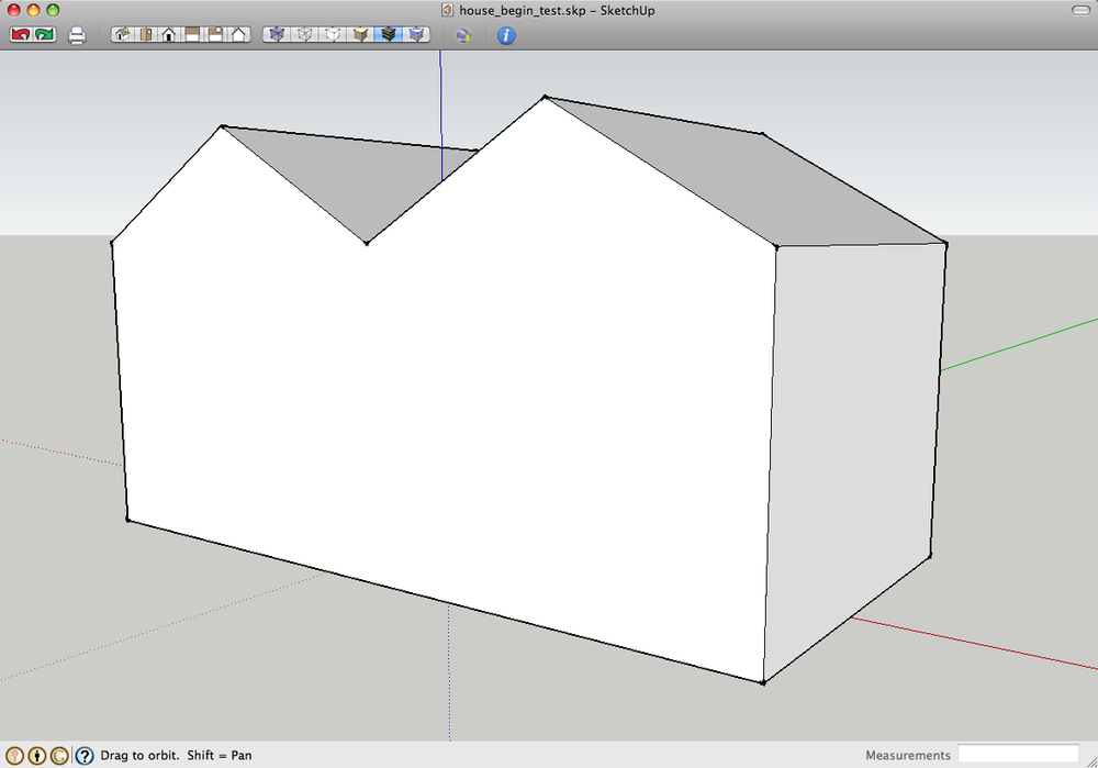
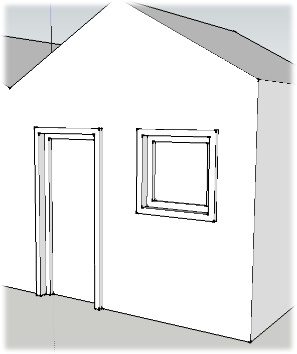
For this exercise, start with a house-shaped box that looks like the one in Figure 4-17. You create and position openings for doors and windows. Later you’ll create framing and trim for these features.
With the Rectangle (R) tool, draw a front door on the house.
Position the door to the left of the midpoint, as shown in Figure 4-18. For this exercise, it’s fine to eyeball the dimensions. Just drag out a rectangle that appears to be a reasonable size.
Figure 4-17. If you don’t have a house model from the previous exercises, you can download house_begin.skp from the Missing CD page at http://missingmanuals.com/cds.Hover over the door’s upper-right corner, and then move horizontally to the right.
When you see a tooltip that says “Endpoint”, move the cursor to the right. As you move the cursor horizontally, you should see a dotted inference line—if not, try moving up or down just a smidgen.
Press and hold Shift to lock the inference.
The thin, dotted inference line becomes a thick, dotted inference line.
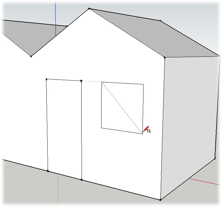
Click-move-click to draw a window, with the top edge the same height as the door.
Your window can be square as is the one shown in Figure 4-18, or it can be rectangular. SketchUp displays a tooltip message when a rectangle is a square or a golden section.
On the left side of your house, draw a large rectangle for a garage door.
You can place the garage door anywhere along the left side of the building. You’ll position it precisely in the following steps.
With the Select tool, click the garage door.
After you preselect the garage door, the face and edges show highlights.
Choose the Move (M) tool and click the midpoint at the top of the garage door.
After you click the midpoint, the garage door moves with the cursor. It’s constrained to moving along the face of the wall.
Press and hold Shift, and then move the cursor to point at the peak of the garage, as shown in Figure 4-19.
The garage door moves horizontally as you move the cursor.
Click to finish the move.
The garage door is centered beneath the peak of the roof.
Using the Offset Tool
The world is full of symmetry—both natural and human made. This fact was not lost on SketchUp’s software engineers; they created the handy Offset tool so you can easily copy and use the existing shapes and edges in your drawing. The Offset tool is in the toolbar, near the Move and Push/Pull tools, or you can choose Tools → Offset. For some tips and details about using the Offset tool, see the box on the next page. In this next exercise, you’ll trim out the window and doors of your house model. Trim out is a carpenter’s term for applying wood trim around something like a door or window. Trim hides the seams and provides a more finished look.
For the purposes of learning SketchUp, the trim out process provides a great introduction to the Offset tool. Before you use the Offset tool, make sure nothing in your model is selected by pressing Ctrl+T (Shift-⌘-A).
Select the Offset tool and then move the cursor over different parts of your house model.
As you move the cursor around your model, auto-selection kicks into action. Different faces are highlighted and a red square snaps to different edges. The square marks the target of the offset operation.
Click once while the red square is on the edge of the window.
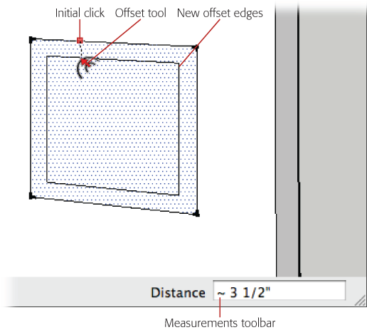
The square locks in place on the edge. Now as you move the cursor, you see another rectangle that indicates the shape to be created by the offset. Drag the cursor away from the opening to create an offset on the outside of the window opening, or drag it toward the center of the opening to create an offset inside. As you drag, the offset distance is displayed in the Measurements toolbar, as shown in Figure 4-21. If you want to be precise, you can type a value in the Measurements toolbar.
Move the cursor toward the middle of the window, and when you’re happy with the size of the window trim, click once.
A new rectangle appears within the original window opening.
Double-click the edge of the inner rectangle.
The Offset tool creates another rectangle inside of the window with the same offset distance.
Use the Push/Pull tool to push back the “glass” at the center. Then push back the frame about half that distance. Finally, pull out the trim so that it’s about an inch or two in front of the surface of the house.
Adjust these features to taste for now. If you want, you can enter precise values in the Measurements toolbar.
Tip
When you’re creating the trim and window frame details with the Push/Pull tool, it helps to change the camera view so you see the details from a slight angle. That makes it easier to judge the distance between the surfaces.
At this point the window trim looks pretty good. You’ve got an inset window frame and an outset window trim. For many buildings, the window and door trim are similar if not identical. When you look at the door, it’s easy to see that it would look good with the same trim around the sides and top, but you don’t really want trim on the bottom, where the door meets the floor. This calls for a little preselection before you apply the offset.
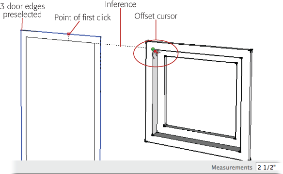
With the Select (space bar) tool, preselect both sides and the top of the door opening.
Click one edge and then hold down the Ctrl (⌘ on a Mac) key. The arrow cursor displays a + sign to indicate that you can add elements to the selection. Click the other two edges to select them.
Change to the Offset (F) tool, and then click the top edge of the door.
Because you preselected the edges of the door, the Offset tool automatically snaps to one of the three selected edges. Even if you hover over other parts of your drawing, it doesn’t change the selection.
When you click the top edge of the door, you see new offset lines for the three edges in the selection.
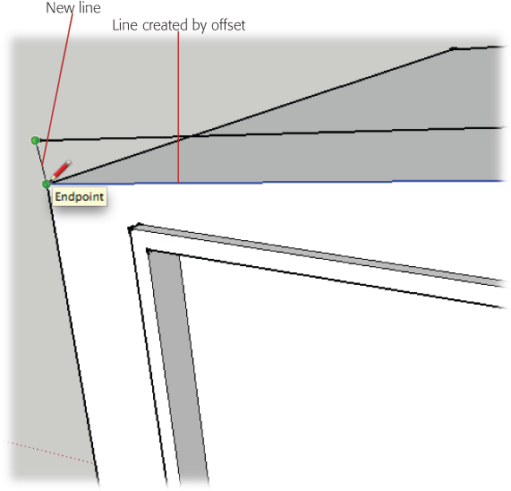
Move the cursor over to the inside corner of the window trim.
With the selection locked in, you can move your cursor anywhere in the drawing window. In this case, you use the window trim as a reference to create the door trim.
When you see a tooltip that says “Endpoint” (as shown in Figure 4-22), click the corner.
SketchUp creates an offset for the door trim that’s similar to window trim. The three edges that were originally selected are still selected, making it easy to repeat the process to create the door frame.
Again click the door’s top edge.
The Offset tool goes into action, once again displaying new edges as you move the cursor.
This time, move the cursor to reference the inside edge of the window frame and then click.
Another set of three lines appears, giving you an edge for the door frame.
Press P to select Push/Pull, and then click the door opening.
After clicking, the face of the door moves back and forth as you move the cursor around the drawing area.
Click the window opening.
When you click the window opening, Push/Pull uses that as a reference for the door and sets the door at the same depth in the wall.
Click the door frame, and then click the window frame.
The door frame is the next section moving from the center to the outside of the door. You set its depth by referencing the window frame.
Click the door trim, and then click the window trim.
The final clicks set the door trim so that it stands out from the wall the same distance as the window trim. Where you’re done, your trimmed out door and window should look like Figure 4-23.
For consistency, you probably want to add trim to the opening for the garage door; however, it doesn’t need an inset frame like the front door and window. You can trim out the garage door using the same technique you used for the front door. Preselect the two sides and the top edge, and then click the top with the Offset tool.
Use the front door trim to size the trim for the garage door. You can use Push/Pull to set the garage door back in the wall, and then use it to pull the trim out from the wall surface.
Building a Roof with an Overhang
As you add details your model begins to look less like a modified shoebox and more like a real house. Another detail that’s important for real houses is a roof with an overhang. The body of the roof holds beams and rafters that support the roof, and the overhang protects the walls and siding from sun and weather. In the real world the laws of gravity and nature seem to have more effect than they do in SketchUp.
In this next exercise, you use the Offset tool to create a profile for your new roof, and then you use Push/Pull to give it shape. The first step is to modify the overall contour of the roof using the Move tool.
Click the roof’s left ridgeline, and move it down in along the blue axis.
When you move the ridgeline along the blue axis, you see a dotted blue line and a tooltip message that says “On Blue Axis”.
When you see the “On Blue Axis” tooltip, press and hold Shift.
The Shift key locks the movement of the edge to the blue axis.
Click the house’s left edge.
The roof flattens, eliminating the ridgeline.
Erase the shared edge.
You no longer need the shared edge that divides the ridgeline; remove it now so it won’t interfere with other parts of the model.
Move the outside edge down just a bit.
Creating a slight slope here helps drain moisture and gives the building a bit of character, as shown in Figure 4-24.
At the front of the house, select the edges that define the roof’s profile.
Your selection should include three lines at the top of the house.
Use the Offset tool to offset the edges up.
You can eyeball this offset, or type dimensions. Something between 6 and 8 inches is appropriate for a roof.
With the Line (L) tool, connect the edges between the original lines and the new lines created by the offset, as shown in Figure 4-25.
You close this new shape by drawing a line on each end. Once the shape is closed, the face fills in.
Choose Push/Pull (P), and then push the new outline of the roof back to cover the rest of the house.
Click the new surface once with Push/Pull, and then push it to the back of the building. You can reference one of the back edges to temporarily align the roof with the back of the building.
Pull out the overhang on the front.
Click the front face again, and begin to pull the face forward to create an overhang. A 9- or 10-inch overhang works well, but you can use any dimension you want.
Pull out the overhang on the sides and the back.
The overhang should be the same on all sides of the building. Use the Measurements toolbar to accurately create overhangs of equal dimensions. After you’ve pulled out all the overhangs, you may notice that the process leaves some extraneous lines.
Note
You can’t just double-click to repeat the overhang distance. This is due to SketchUp’s interior (white) and exterior (blue) face issues. For more details, see Double-Clicking with Push/Pull.
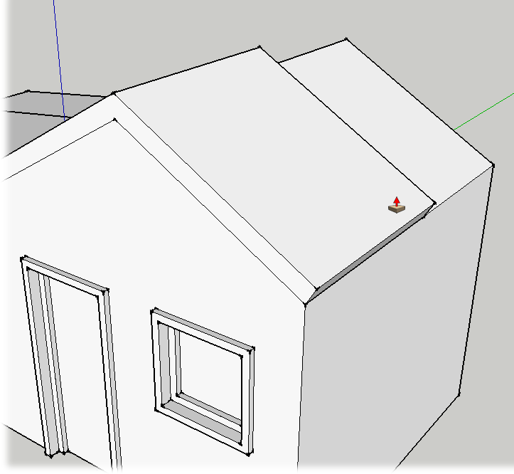
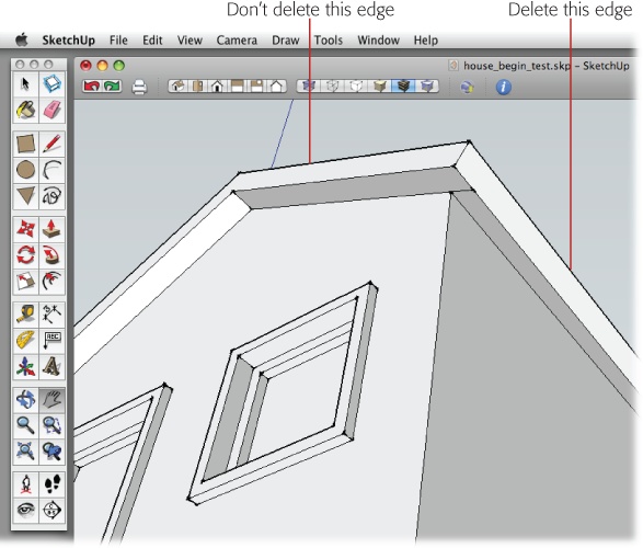
Change your view so you can see the bottom of the overhang, and then erase the extra lines.
As shown in Figure 4-27, delete the shared edges that separate faces on the same plane. Don’t delete the edges where the roof changes angle; that also erases the faces.
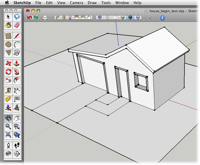
Orbit (O) around the place and admire your construction skills.
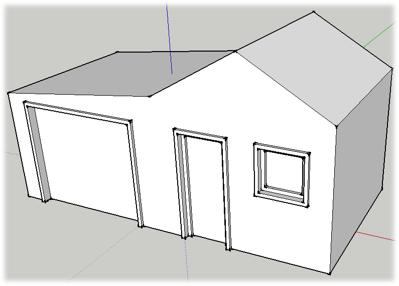
Unless you’ve gone off on a creative tangent, your model looks something like the house in Figure 4-28. You’ll take care of the initial landscaping in the next few steps.
Initial Landscaping: Front Walk and Driveway
You’ll do some more extensive landscaping in the next chapter, but for now you can give your house a plot of earth and a couple of basic paths for cars and people. These basic features are created using the Rectangle and Line tools. You want to draw these elements at the ground level, so it’s best to change to the top view before you begin. Once you’ve drawn the outline of the yard at ground level, the other shapes and paths will align to that surface.
Change to the Top view.
This gives you a bird’s eye view of your estate. You may want to zoom out a little so there’s room around the house to create a yard. Press Z to change to the Zoom tool, and then drag to change the view.
With the Rectangle (R) tool, click-move-click to draw a rectangle around the house to represent the yard.
Give yourself enough room for the kids and dog to play. And who knows, some day you may want to add a pool.
Right-click (or Control-click) the face of the new yard, and choose Reverse Faces from the shortcut menu.
Because it’s a two-dimensional shape, it’s more than likely that your rectangular yard is displaying the blue face that indicates an interior. Reversing faces changes its color to white.
Select the Line tool, and then draw two lines to create a drive from the garage to the edge of the yard.
Use Figure 4-28 as a reference for placing the edges of the driveway. It’s easiest just to click the point where the garage door frame meets the yard.
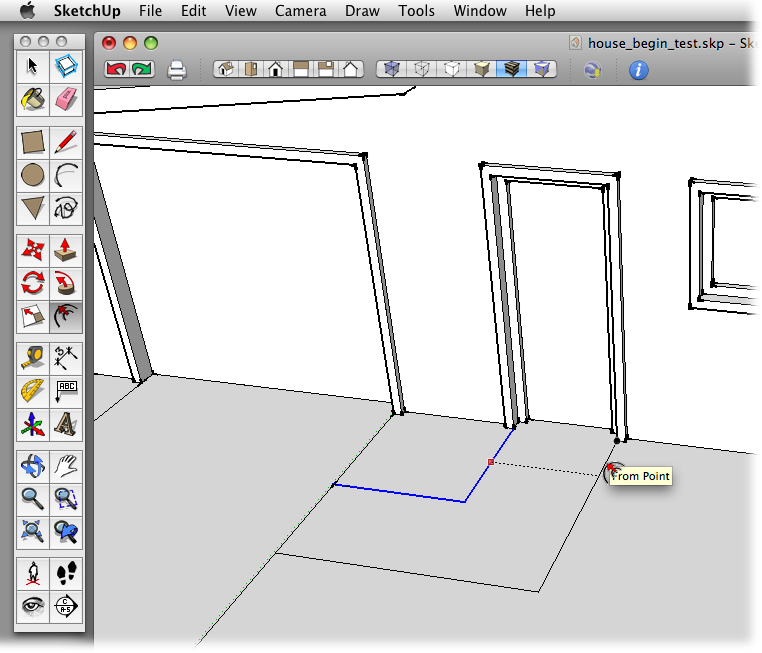
Use the Line tool to create the left edge of an L-shaped path from the door to the driveway.
Click the point where the front door meets the yard, and draw a short line toward the street. Then create another line segment that turns to the driveway, shown in Figure 4-29.
Choose the Select (space bar) tool, and then select the two lines that mark the edge of the path.
When they’re selected, the thin black lines become thick blue lines.
With the Offset (O) tool, click the selected lines, and then click the other corner where the front door meets the yard.
Your walkway has two edges and is the same width as the house’s doorway.
Save your model with the name house_finished.skp/.
Not bad for a day’s construction. You can use this model in the next chapter, where you tackle fence building and learn about the joys of SketchUp components.
Get Google SketchUp: The Missing Manual now with the O’Reilly learning platform.
O’Reilly members experience books, live events, courses curated by job role, and more from O’Reilly and nearly 200 top publishers.

