In this chapter, youâll gain your first experience with Flashâs vector drawing tools. Many of Flashâs tools are similar to those available in other applications, so you may be able to apply some of what you already know to Flash. However, some of Flashâs tools behave in unique ways. For example, Flash builds everything you draw using vectors. So, although using Flashâs Brush tool will feel similar to using a brush tool in a bitmap editing application such as Photoshop, what you draw will actually be a vector shape.
Flashâs selection tools also behave a bit differently than those in a typical drawing application. You can select a shapeâs fill or stroke independently, and even separate the two. Also, using the Lasso tool, you can freely draw a selection path across any shapes and work only with the selected portion of those shapes. This combination of pixel-and vector-based drawing approaches makes creating Flash assets a natural and immediate experience.
If you are comfortable with traditional vector drawing applications, donât worry; you will also find a Pen tool for creating Bezier curves complete with vertices and control points in Flash. However, even if you are unfamiliar with these terms, youâll still be able to jump right in and start creating.
Your first proect is to create a graphic you might use in a psychedelic poster illustration of guitar legend Jimi Hendrix. Youâll begin by drawing a box, which is one of the most commonly used shapes in design and a frequently used metaphor in this book. Next, youâll customize your lines and fills, add a vibrant array of colors, and draw Jimiâs silhouette. The techniques used in this chapter are the first steps in learning to create assets within Flash, and they are commonly used for animation, illustration, game development, application design, and virtually anything else youâll do in Flash.
Drawing a box is easy, so in this proect youâll also look at a few ways to enhance your drawing with color and stroke properties. If youâre new to Flash, fear notâyouâll feel comfortable in no time.
When you launch Flash for the first time, the Start screen appears, as shown in Figure 1-1. This is merely a handy launch utility, and if you find it intrusive, you can disable it in the lower-left corner of the panel. One of the reasons you may want to use the panel is that it keeps track of the last 10 documents you opened (although you can also access this list via the File â Open Recent menu command).
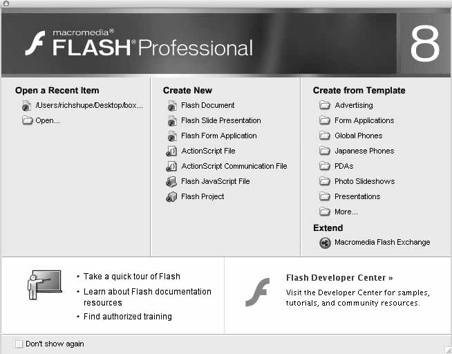
The second column of the Start screen allows you to create a new Flash document. Figure 1-1 shows the Start screen from Flash 8 Professional, which includes additional file types. Youâll learn a little more about some of these files later in this book. In Chapter 13, youâll also learn how to use templates. For now, though, youâll focus on your first steps.
Note
The bottom portion the Start screen provides quick links to Internet resources to help you learn Flash. This area may reflect automatic online updates provided by Macromedia, so your screen may vary slightly.
Before you can start designing, you need to create a new Flash file:
If you havenât already, copy the CD-ROM source files and folders to your hard drive. Hereafter, the location where you store these files will be called your âworking directory.â Also, be sure youâre running Flash 8. (Some features of this book require the Professional version. See âGetting Startedâ in the Preface for more information.)
Note
Flash documents are often called FLA files. This is the convention used in this book, although some developers reserve this term for the final compressed file format used to distribute Flash files. Files in this format use the .swf (pronounced âswiffâ) extension. SWF files are compiled when you test or publish your FLA files.
Under the Create New heading of the Start screen, or by using the File â New â Flash Document menu command, create a new Flash document. You will save this file using the .fla extension (sometimes pronounced âflahâ). This file type is the basis for virtually every Flash project.
Save your new document as box.fla in your working directory, using the File â Save menu option. Alternatively, you can press Ctrl-S (Win) or Cmd-S (Mac) to save the file.
Note
Throughout this book, exercises will frequently build upon previous exercises. Usually, youâll be told when you no longer need a file, or when to start another file for a new topic or for experimentation. So, as a new series of steps begins, assume youâre continuing your work, unless otherwise stated. You will also occasionally be prompted to compare your work to the sample files at major milestones. Feel free also to check your progress against interim steps at any time.
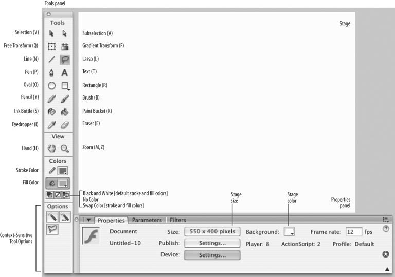
Now, take a moment to look around the world of Flash. Notice the Tools panel, shown in Figure 1-2. (If your Tools panel isnât visible, open it using the Window â Tools menu command.) Many tools will look familiar if youâve worked with other graphics programs. As you roll your cursor over each tool in the panel, a tool tip indicates its name and shows its keyboard shortcut in parentheses. For example, you can select the Rectangle tool by pressing R. The Options portion at the bottom of the Tools panel reflects options for the currently selected tool. This context-sensitive area changes depending on which tool is active.
Begin by drawing a rectangle as a starting point for a new design:
In the Tools panel, select the Rectangle tool, indicated in Figure 1-2.
Roll your cursor over the Stage (the large white area in the document window, also seen in Figure 1-2). Your cursor should look like a cross-hair.
Click and drag somewhere on the Stage to create a rectangle. As you can see, using the Rectangle tool in Flash is similar to using the same tool in other programs.
You are probably familiar with the Undo command from your experience with other programs. When you use the Edit â Undo menu command, or press Ctrl-Z (Win) or Cmd-Z (Mac), Flash will attempt to undo your last action. (Some things canât be undone; in this case, Flash will try to warn you before proceeding.)
Take a moment now to undo your rectangle creation. If you followed the steps described previously, you should now have an empty Stage. If not, continue to use the Undo command until your Stage is empty.
By default, Flash will store the 100 most recent undoable changes you have made to your open documents. Several hundred levels of undo can be stored, but they require memory. With each additional step you store, more system memory is consumed. Refer to Appendix A for information on how to change this setting.
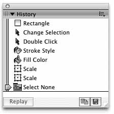
You can see the undo list in action by opening the History panel, shown in Figure 1-3, using the Window â Other Panels â History menu command. Once you have opened this panel, draw a few boxes on the Stage again, and watch the history list grow. After adding a few items, use the draggable arrow on the left side of the panel to slide up the list. As you move further back in history, you will see your boxes disappear as your actions are undone. Great, huh? It gets better. In Chapter 2, youâll learn how to use the History panel to help automate tasks.
Flash 8 now offers both Document Undo and Object Undo modes. Document-level undo maintains a single list of all undoable actions for the entire Flash document. Object-level undo maintains separate lists of your actions for each major object (such as buttons and similar items) in your document. Object-level undo is more flexible, because you can undo an action in one object without having to also undo more recent actions in other objects.
However, it can sometimes be advantageous to use document-level undo, and you should bear in mind that switching between the two modes will clear your current history. (Your document will not be affected, but your history list will be emptied.) So, experiment to see which you prefer, and be cautious when switching undo modes.
Drawing a perfect square is simpler than it sounds. All you need to do is hold down the Shift key while drawing the square. This technique, common to many graphics applications, is called âconstraining.â This is because the Shift key constrains the shape into a square while itâs being drawn, even if you accidentally describe a rectangle with your mouse movement. This is a great way to ensure that your squares are actually square. The same rule applies to the Oval tool for drawing perfect circles and the Line tool for drawing straight lines.
What if you want to create a box that is exactly 300 x 300 pixels? In this case, you can use numeric input to get the exact shape you want. Hereâs how:
If you havenât already done so, delete everything on the Stage.
Select the Rectangle tool, and click and drag on the Stage to draw a rectangle.
When youâre done, choose the Selection tool (shown in Figure 1-2) from the Tools panel.
Double-click inside the box you just drew to select both the box and its border.
With the box selected, locate the Properties panel, shown in Figure 1-4. (If necessary, open it with the menu command Window â Properties.) The Properties panel looks different in this figure than it did in Figure 1-2 because its contents change depending on what is selected. At the bottom of Figure 1-2, the Properties panel displays the Stageâs properties. In Figure 1-4, it displays properties for the selected rectangle.
The W and H fields in the Properties panel represent the rectangleâs width and height. The relative proportions of width and height can be constrained by clicking on the lock icon to the left of these fields. In this case, this is fine, as you are drawing a square. However, if you want freedom to enter any width or height, youâll need to click on the icon to unlock it, as pictured in Figure 1-4. Enter 300 for the width and 300 for the height. You now have a precisely sized rectangleâa perfect square.
Save your work.
Note
Donât worry if you canât get an exact number when entering property values. Flash does its best to give you the value you request, but it isnât always easy to achieve exact sizing or positioning at the sub-pixel level. If you get values like 299.9 or 300.1, the difference will usually be unnoticeable.
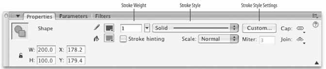
You may have noticed, during your experimenting, that you havenât been getting nice sharp corners. Flashâs default behavior uses rounded stroke corners and end caps, but Flash 8 finally introduced the ability to customize the cap and join settings of your strokes. The Cap setting dictates the appearance of the ends of the lines, while the Join setting defines the appearance of corners. As you can see in Figure 1-4, both settings can be found in the far right of the Properties panel when a shape with strokes is the active selection.
Caps can be set to None (the line ends precisely at the end point), Round (a round cap is placed on each end of the line), or Square (a square cap is placed on each end of the line). Joins can be set to Miter (sharp corner), Round, (rounded corner), or Bevel (two-point corner).
Figure 1-5 shows the results of each setting. All the line widths are the same, and all shape end points terminate at the dotted lines. From top to bottom, the features used are: 1) Cap: None, Join: Miter; 2) Cap: Round, Join: Round; and 3) Cap: Square, Join: Bevel.

Note
Cap settings add to the apparent length of a line. Notice in Figure 1-5 that although all the lines end at the same horizontal or vertical positions, those with caps appear longer.
When youâre drawing or editing a shape, Flash independently colors fills and strokes. You can change the colors via the Tools panel or the Properties panel when a shape or shape tool is active. In both locations, a small pencil icon indicates the stroke color, and a small paint bucket icon indicates the fill color.
There are two simple ways to change a shapeâs fill or stroke color. First, you can change the fill color of a selected shape using the pop-up color swatch utility:
Choose the Selection tool from the Tools panel, and click once inside the box on the Stage. The fill area will appear as if seen through a screen, indicating that it is selected.
In the Properties or Tools panel, click on the Fill Color swatch. A palette of colors will pop up, and youâll be allowed to select from the default web-safe swatches. A white box with a red line through it at the top of the pop-up indicates that no fill will be used, allowing underlying assets to be visible within the borders of the shape.
Deselect the box to view the results. You can deselect by using Edit â Deselect All, or by clicking in any unoccupied area of the Stage or Work Area (the area surrounding the Stage). Deselecting is often required to avoid editing an active element, and it will soon become second nature.
Fills and Strokes
Unlike in many other drawing programs, Flash elements are drawn using separate fills and strokes. Although this can take some getting used to, it can also be very helpful. The best way to understand how fills and strokes work is to do a little experimenting. You may want to open a new document so that you can tinker while reading without affecting your ongoing exercises.
A fill is the area of color that fills the inside of a stroked shape or constitutes the body of a borderless shape. For example, if you draw a free-form blob on the Stage, the colored area inside its border is its fill. The colored area is called a fill even if no border surrounds it.
A stroke is the border or line surrounding a shape. Strokes can have six styles, the most common of which are solid, dotted, and dashed. Each stroke type can be customized with a variety of settings, all of which can be found within the Properties panel when a line or line-making tool is active.
Flash allows you to select individual fills and strokes separately, if you desire. You can select only a fill, or even only one side of a multi-sided stroke. Selecting a contiguous fill, or a single part of a multi-part stroke, requires one click. To select an entire contiguous stroke, double-click on the stroke only. To select both a fill and its stroke, double-click on the fill. See Figure 1-6 for a comparison of single-clicking and double-clicking a multi-part stroke.

If you want to work with an entire shape (fill and stroke) but accidentally only select one, the remainder of the shape will not be edited. This can happen when draggingâfor example, you may drag a fill and leave the stroke behind.
If this happens, undo your change and double-click, or press the Shift key while selecting multiple objects, to include all the desired elements in your efforts.
You selected just the fill to practice, and to show that the colors of selected shapes can be changed directly with the color swatches. Next, youâll use the Ink Bottle tool to exclusively change the color of a stroke, regardless of whether or not it has been selected. The Ink Bottle tool is adjacent to the Paint Bucket tool in the Tools palette.
You may be familiar with the Paint Bucket from experience with other graphics tools. You can use it to change a fill color by single-clicking within the fill area. Think of the Ink Bottle tool as a Paint Bucket for lines. It will apply your preferred stroke attributes to any shape stroke you click on:
Choose the Ink Bottle tool, click on the Stroke Color chip (indicated by the pencil icon), and pick a color for your stroke.
If you wish, experiment with some of the other stroke attributes in the Properties panel, such as thickness, cap, and join settings. Editing strokes will be discussed further in a few minutes.
To view the results, with the Ink Bottle tool active, click on a shape stroke. The stroke should change to reflect your chosen attributes while the fill remains unaffected.
Now that you know how to add colors to shapes, youâre probably asking yourself, âWhat if I donât want to use one of the default colors available in these tool swatches?â No problem. There are a few ways to create your own custom colors.
If you just need a quick color, which you may not use often, you can create a color on the fly, you can take advantage of two options in the color swatches pop-up palette that appears when you select a stroke or fill color. The first option is to use the hexadecimal entry field in the top left of the swatches pop-up. This field allows you to enter hex color values to specify any color numerically. If you are familiar with HTML, you will likely be comfortable with this method.
The second option is to use the color picker icon in the upper right of the swatches pop-up. This will bring up your operating systemâs color picker, which will allow you to select colors using a variety of methods used by your system. If you work with color in other applications, you may be familiar with this utility already.
Another handy feature in Flash 8âs swatches pop-up (Figure 1-7) is the ability to control your colorâs opacity via the Alpha setting. Colors with an alpha value of less than 100% have some transparency, allowing your colors to mix on the Stage.
The swatch pop-up utility is great for quick access, but what if you need more control? Enter the Color Mixer.
The Color Mixer
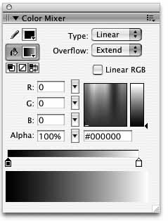
The Color Mixer panel, shown in Figure 1-8, gives you some great options for changing strokes and fills, and even enables you to change the fill completely by converting it to a gradient.
Here is a breakdown of the options for the Color Mixer:
- Stroke color
Changes the color of the stroke. You can access your operating systemâs native color picker using the icon in the upper right of the pop-up palette. This allows you to specify colors from spaces other than RGB, such as hue, saturation, and brightness (HSB).
- Fill color
Changes the color of the fill. See Stroke Color for additional information.
- Swatch utilities
Sets the stroke and fill colors to black and white, respectively; removes the selected stroke or fill; switches the stroke and fill colors.
- Fill Type (menu)
Changes the fill style. Options include None (which deletes the fill), Solid (for a solid, one-color fill), Linear (for a gradient that blends on a linear path), Radial (for a gradient that blends outward, in a circular path, from a focal point), and Bitmap (for a fill made of tiled bitmap images). Additional gradient options are discussed in the main text.
- Gradient Overflow (menu)
Visible only when a gradient fill type is selected; determines how the gradient is mapped when exceeding the range of the Gradient Transform tool. Options include Extend, Reflect, and Repeat.
- RGB input (three separate entry fields, pop-up sliders)
Changes the density of the red, green, and blue (RGB) colors in a fill.
- Alpha
Sets the percentage of opacity for a solid fill (or the currently selected Color Proxy slider for a gradient fill). Zero percent alpha makes it invisible, while 100% alpha makes it opaque.
- Color chooser
Provides a quick, visual way to choose any color. Simply click on the color chooser and drag the cursor around to locate the color you want.
- Brightness slider
Changes the brightness of the current color.
- Hexadecimal input
Changes the color by accepting hexadecimal values. Commonly used in HTML, hex values are six-digit number and/or letter (AâF) combinations that represent colors, such as #000000, which represents black, or #FFFFFF, which represents white.
- Gradient color swatches
Changes the colors used in gradients. Between 2 and 15 colors can be used for each gradient.
- Current color
Displays the currently selected color.
When creating solid colors, like the colors youâve been using so far, in some ways the Color Mixer is not unlike the color swatches pop-up. However, instead of limiting custom color creation to hexadecimal value entry and the system color picker, it has its own color chooser. A small box presents a graduated tone of hues from left to right, and decreasing brightness from top to bottom. You can pick a color value with your mouse and then use the vertical slider to increase or decrease brightness. As youâll see in a moment, you can also save your color choice for later reuse. See the sidebar âThe Color Mixerâ for a look at its interface and a little more detail on its functionality.
When creating gradients, the Color Mixer is required. Next, youâll use it to create a gradient that will be the basis for a psychedelic look in a 1960s-style Jimi Hendrix poster illustration:
If youâve been experimenting, undo your changes or use the File â Revert menu option. As long as you havenât saved since last instructed to do so, this will revert your file back to where you left offâa 300 x 300 pixel square with fill and stroke.
Select the fill and choose Window â Color Mixer to open the panel shown in Figure 1-8, in the sidebar âThe Color Mixer.â
In the Color Mixer panel, select Linear from the Type drop-down menu. The solid color automatically changes to a linear gradient. A thin bar, showing the gradient in progress, allows you to edit the gradient via the mini-swatches below it. (A new menu, called Overflow, also appears; youâll learn about that later.)
The small color chips beneath the gradient color bar have arrows pointing to the focus point of each color. These swatches define the colors used in the gradient and slide left and right to define the position of each color.
To change the gradient, change the color of these swatches in one of two ways. Double-clicking a chip enables you to choose a color from the familiar swatch pop-up utility. For more flexibility, you can select a chip with a single click and enter RGB or hexadecimal values in the input fields, or use your mouse with the color picker and brightness slider. Both techniques allow you to add an alpha value to a color to achieve transparencies of 0 to 100%.
You can use from 2 to 15 swatches, and you can remove swatches by dragging them down and away from the gradient preview bar. Change the gradient hues now, and add two more for big splashes of color:
Double-click on the leftmost gradient color swatch, and pick a bright yellow color from the color palette. If you want to try to match the sample files (although thereâs no reason you must), the yellow is HEX #FFFF00, or RGB 255, 255, 0.
Next, double-click on the rightmost gradient color swatch to change the end color for the gradient. Choose a vibrant purple. The sample file uses HEX #660099, or RGB 102, 0, 153.
Now add a new chip by clicking directly beneath the gradient color bar, approximately one third of the way along the span of the gradient, from the left. It will assume the color immediately above it. Change its color to HEX #FF0000, or RGB 255, 0, 0, for bright red.
Add another color halfway between chips two and four, or approximately one third of the way along the span of the gradient, from the right. This time enter a HEX value of #3399FF. You now have a colorful linear gradient.
Experiment by dragging the chips left and right to give each color more or less prominence. When youâre done, place the first chip at the far left, chips two and three at one-third and two-thirds from the left, and the last chip slightly short of far right. This will give purple a bit more weight and will help demonstrate another feature in a minute or so.
To create a background more like the psychedelic posters from the 1960s, change the Type drop-down menu choice to Radial. This changes the gradient so it blends outward from a central point instead of along a linear path.
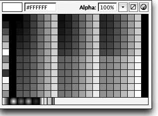
If youâre satisfied with your gradient, save it for later use. If itâs not already visible, choose Window â Color Swatches to view the Color Swatches panel. When you move your mouse over the empty white area, the pointer will change into a paint bucket. Click the mouse and, since the currently active new color is a gradient, the gradient will appear in the bottommost row of swatches. Now you can use the gradient anytime later in this file, even if you create a new gradient in the meantime.
Save your work and leave this file open.
The stroke for this image could be improved to better fit with the illustration style, so change it from a solid line to something funkier:
Deselect the fill of the box, and double-click the stroke to select the entire stroke.
In the Properties panel, give the stroke a dark maroon color.
Click on the Stroke Style drop-down list, shown in Figure 1-4, and choose the next-to-last style. (The styles arenât named in the menu, but it looks a bit like splattered paint.)
Using the Stroke Height text field or slider in the Properties panel, set the stroke weight to 10.
Deselect the stroke to see what it looks like. Your stroke should be 10 pixels wide and appear as an array of spots that resemble paint splatters. Things are looking good now, but the stroke doesnât seal off the border as well as it could, so modify it to fix the problem.
Select the entire stroke again. In the Properties panel, click the Custom button to open the Stroke Style dialog box. The Type drop-down should already be set to Stipple (unless you chose a different type of stroke earlier).
Set Dot Size to Medium, Dot Variation to Varied Sizes, and Density to Very Dense. This tightens up the stroke to seal up the edges of the fill it surrounds. Click OK and deselect the stroke to see your work by clicking somewhere outside of the box. Nice, huh?
Save the file, but leave it open.
Often, you canât tell when starting a drawing how big or small it needs to be, and sometimes creative tangents bring about change. Here, you need to make your illustration more impressive by filling up the Stage.
Quick, inexact scaling is very simple in Flash. All you need to do is activate the Free Transform tool (Q) and use your mouse to drag one or more of the active drag locations. You can resize by dragging any of the handles; the cursor will temporarily change to a double-headed arrow to indicate that scaling is possible. (You can also skew by dragging the sides, or rotate by dragging outside one of the corner handles. Temporary cursor changes will also indicate that these features are possible.)
Here, however, you need exact resizing and positioning capabilities, so youâll use the Properties panel. The Stage is rectangular, but the image is square, so you have to make one change first. If you resize the background box as is, changing its shape from a square to a rectangle, the radial gradient fill will distort. Youâll learn later how to position and scale gradients directly, but in this exercise youâll delete the fill and replace it after resizing the box. Hereâs how:
First, make sure your background gradient has been saved in the Color Swatches panel, as described earlier. If not, use the Eyedropper tool to pick up the gradient from the background and then click anywhere in the empty white area of the Color Swatches panel.
Now you can safely select the gradient fill and delete it using the Backspace or Delete key on your keyboard.
Select the boxâs stroke and, using the Properties panel, set the width (W) to 550 and the height (H) to 400. Remember, you may need to unlock the padlock icon to change the boxâs width and height independently. The stroke now matches the dimensions of the Stage.
Also in the Properties panel, change the boxâs X (horizontal) and Y (vertical) coordinates to 0. After pressing Tab or Return to register the values, this aligns the stroke to the upper-left corner of the Stage.
Activate the Paint Bucket tool and switch the fill color using the pop-up swatches. You should now see your gradient in the bottom row with the default gradients. Select it.
Look in the Paint Bucket toolâs Options area, located in the lower portion of the Tools panel, and make sure the Lock Fill option is disabled. Use the Paint Bucket tool to apply the gradient to the background box. Notice that the radial gradientâs center point is determined by the position of your click. Click several times inside the box to change the center point for the gradient until you are happy with the look.
Next, activate the Lock Fill option and try to apply the fill again. The Lock Fill option prevents the fill from being changed. Now that youâve seen the effect of this option in both states, disable it once again, so you can edit the fill later. If the scale or position of the gradient isnât exactly the way you want it, donât worry. Youâll soon learn how to change that.
Save your work. If you want to compare your work with the sample files, your file should look like box_03.fla in the 01 folder in your working directory.
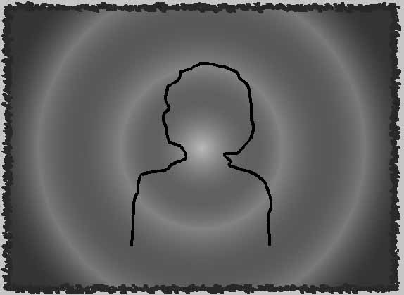
Adding a silhouette of Jimi Hendrix in the foreground of this gradient will finish off the design nicely. If your drawing skills arenât great, donât sweat it. The silhouette of Jimi, just like the rest of this image, can be as psychedelic as you want. The objective is to see how the Pencil tool can be used to draw shapes freehand:
Choose the Pencil tool from the Tools panel. In the lower portion of the panel, the context-sensitive Options area includes two options. Youâll use the Object Drawing option in a moment. For now, this should be disabled. The Pencil Mode option offers you a choice of Straighten, Smooth, and Ink. These options will help you draw straighter lines, create smoother curves, or work freehand, respectively. Set the option to Smooth. In the Properties panel, set the stroke weight to 5, set the stroke color to black, and change the stroke style back to a solid line.
Click and drag inside the box to draw a silhouette of Jimi, like the one in Figure 1-9. Donât let the ends of the stroke touch the border of the box. (Youâll learn why in a moment.)
Note
If you prefer not to draw the silhouette yourself, open hendrix_silhouette.fla, located in the 01 folder in your working directory. Double-click to select the entire stroke, choose Edit â Copy to copy it to your clipboard, and then return to box.fla and choose Edit â Paste in Center to paste it into box.fla. Close hendrix_silhouette.fla by choosing File â Close when youâre done.
You can stop and start as much as you want using the Pencil tool, so feel free to use as many lines or curves as you need. If you make a mistake, either undo it or just go with it. In creative situations like these, mistakes can sometimes be as inspirational as the lines you draw intentionally.
If youâre not satisfied with your drawing, try smoothing the stroke with the Selection toolâs Smooth option in the Options section of the Tools panel. This is similar to the Pencil toolâs Smooth option, but it allows you to smooth strokes after theyâve been created. Try this:
Select the stroke you wish to smooth. If the lines are all connected, double-clicking will select them all. If not, press Shift and select each line individually until you have selected all of them.
Click once on the Smooth option at the bottom of the Tools panel. This makes the stroke smoother. If youâre happy with the new look, leave it alone. If not, click Smooth one or two more times until youâre satisfied. The trick is knowing when to stop smoothing it. Making it too smooth will diminish the hand-drawn quality. Deselect the stroke when youâre done.
Choose the Paint Bucket tool, and change the fill color to black using the Properties panel. With the Paint Bucket tool active, click once inside the outline to fill in the silhouette of Jimi.
Did the entire image turn black? If it didnât, thatâs fine. In fact, this is the desired result, as it shows that when you drew your line you fully enclosed the area within it (either by connecting the strokeâs end point with its starting point, or by connecting both ends of your stroke with the border of the box).
If the entire image did turn black, donât worry. What this means is that when you drew the silhouette, you didnât fully complete the Hendrix outlineâa gap remained that allowed the fill color to âspill outâ and fill any connected area with the black color. You can fix this by closing the stroke and sealing off the fill area:
Undo the last step to remove the black fill from the image.
Using the Pencil tool, make sure the entire outline is complete, including a line across the bottom of the silhouette.
Activate the Paint Bucket tool again, and display the Gap Size menu from the Options section of the Tools panel. The Gap Size option dictates how large a gap Flash will bridge for you when applying a fill with the Paint Bucket tool. Choose Close Small Gaps from the menu and click inside the shape to see if the fill is applied properly. If not, choose Close Medium Gaps and try again. If that doesnât work, choose Close Large Gaps, and the fill should be applied.
Save your work.
If you connected your silhouette border to the box stroke, your results may differ slightly from the descriptions in some upcoming exercises. Feel free to continue with that in mind, or open box_05.fla to continue.
So far, youâve been using Flashâs default Merge Drawing mode. In this mode shapes can interact with one another, merging together when they overlap. For example, if the corners of two squares overlap, the frontmost shape will âknock outâ the underlying shape, effectively deleting it, as seen in the top of Figure 1-10. This behavior contrasts with that of the newly introduced Object Drawing mode, which will be discussed shortly.

What are the implications of shapes merging? If you didnât save your work at the end of the last sequence, do so now, and then try this with your current file:
Activate the Selection tool, select the black fill you just applied to the silhouette, and then delete it. Everything inside the fill area is removed, including the gradient previously behind the silhouetteâs fill!
Undo the last step. Youâll need the silhouette fill for something else in a minute.
At first you may think this is a problem, but it can be very useful, and you can prevent it from happening, if you wish. First, however, look at a few simple examples of how Merge Drawing mode can be advantageous. If you recently saved your work, feel free to experiment.
Select the Line tool and draw a line all the way through your artwork, from outside left to outside right. (This is arbitrary, but ensures that the line goes completely through the box and protrudes on either side.) Now choose the Selection tool and click once in various regions of your art. Youâll see that the line has effectively segmented your art, allowing easy selection of smaller pieces.
Next, select the Brush tool. This will show you a good example of how unprotected shapes can be altered in creative ways. In the toolâs Options area, experiment with the different Paint modes. Paint Normal will behave the way you likely expect. Paint Fills, however, will paint only fills, leaving strokes unaffected. Try Paint Behind and Paint Inside to see how they work, too.
Finally, try one last thing. Select the Lasso tool, and freely select any combination of fill and stroke. With a selection active, you can move it, or delete it, as before. The Merge Drawing mode and the Lasso tool make selecting partial fills and strokes very easy and natural.
When you donât want shapes to merge together, there are a few ways to prevent this from happening. In just a few minutes, youâll learn how to convert shapes into another type of Flash asset. Also, in Chapter 3 youâll learn how to add new layers to prevent shapes from ever touching each other. However, you still need to know how to protect existing shapes in the same layer. The first approach youâll practice is making a group from a shape:
Select the fill and outline (stroke) of the Hendrix silhouette. Press Ctrl-G (Win) or Cmd-G (Mac). This creates a group of the fill and stroke so they can easily be moved together (i.e., they cannot be edited separately). A light blue bounding rectangle appears around the silhouette when itâs selected, indicating that this is no longer a shape. In this case, it is now a group.
Drag the group to the right. Youâll see that the area under the silhouette is still empty, but if you deselect the silhouette and then move it again, you will find that this time the move does not affect the gradient beneath it.
Save your work. If you wish, compare your file to box_06.fla.
Traditionally, you probably think of a group as two or more items treated as a single entity, and the same is certainly true in Flash. However, as youâve just seen, a group in Flash has another important purpose. By grouping the parts of a shape, you ensure that the shape can no longer be altered by another shape. Thus, grouping single items is an attractive solution to unwanted shape merging.
What if you want to edit a shape that has been grouped? Although the shapes no longer seem editable, there are two ways to satisfy this need.
First, if you double-click a group, the surrounding assets will appear to dim, and the group will become editable. This is because you are effectively âinsideâ the group and can edit it as if it were a shape. When you are finished editing, you can double-click elsewhere on the Stage to go back âoutsideâ the group. This is useful when you want the shape to continue to be protected from interaction with other shapes.
Note
When inside a group, if you look at the very top of the main document window (to the right of the word âTimelineâ), you will see a series of icons from left to right that represent a nested hierarchy of objects that you are editing. The last one will likely say âGroup,â indicating where you are. You will read about this in greater detail later in this book, but for now bear in mind that if you ever get stuck and donât know what youâre editing, you can look to this area and click icons to the left until youâve walked your way back to where you want to be.
Second, if you break apart a group, it will return to behaving like a shape. To do this, first select the group and then access the Modify â Break Apart menu command (Ctrl/Cmd-B). Be sure you want to do this, though, because it means that other overlapping shapes will again affect the shape.
Both of these techniques are very useful and can be applied to many different types of Flash assets. Youâll see them again when you look at other types of native Flash assets, such as buttons, but they apply to other editable items as well. For example, if you break apart a block of text, the selection will turn into a group of individual letters. If you again use the Break Apart command, those letters will turn into shapesâthey will not be editable as text, but can be fully manipulated as shapes.
Think of breaking apart assets as âgoing down to the next smallest editable item.â This will become clearer with more practice.
Now that you know about groups, you can prevent existing shapes from being deformed by other shapes. But you still have a big hole in your gradient background that needs repair. Hereâs how to fix it:
In the Color Mixer panel, change the Fill Type from Solid to Radial. Your previous gradient should appear again. If not, use the eyedropper to pick it up from your saved color swatch or the remaining background.
Next, use the Selection tool to select the remaining gradient and delete it.
Switch to the Paint Bucket tool so you can fill the border with an intact gradient, but first check again to make sure the Paint Bucket toolâs Lock Fill option is still disabled. This time, click in the upper-left corner of the background box to apply the gradient. The effect youâre looking for is a bright, vibrant sun radiating rays of color. Deselect the gradient to see how it looks.
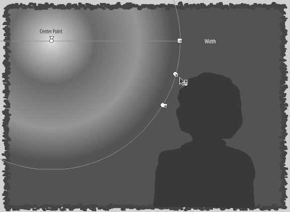
With the gradient deselected, activate the Gradient Transform tool (F). Click the gradient fill to position and scale the gradient the way you want it. The Gradient Transform tool will display a circle with five control points on it, as seen in Figure 1-11.
Use the Center Point control point (the circle in the upper-left corner of Figure 1-11) to position the sun where it appears in the figure. (The triangle is the Focal Point control, which is not used in this exercise.)
Use the Scale control point (the second icon down on the right side of the circle) to scale your gradient until it resembles the gradient in Figure 1-11. As you can see, the last color in the gradient (purple) extends to fill the rest of the box. This is more like a traditional sun. Save your work so you can revert to this design if you prefer it.
See if you can make your sun a bit more psychedelic. Switch to the Selection tool and select the gradient. In the Color Mixer, change the Gradient Overflow setting to Reflect. Your file should now look like Figure 1-12.
The Gradient Overflow option dictates what the gradient will do when it extends beyond the size you set with the Gradient Transform tool. Youâve seen two of the overflow options in action: Extend continues the last color, and Reflect reflects the gradient, reversing the order of its colors until the area is filled. A third option is Repeat, which starts over at the first color in each cycle until the area is filled. Pick the look you prefer and save your work.

Youâve already learned how to protect a shape from merging with other shapes by grouping it, but thereâs a faster way to achieve this result as you are drawing. The Object Drawing mode, introduced in Flash 8, essentially draws shapes that are âpre-grouped.â (The results are actually called drawing objects, but the effect is the same.)
Add a couple of stars to your illustration to practice:
Click and hold the Rectangle tool, and select PolyStar Tool from the pop-up menu. You can use this tool to create polygons or stars with your preferred number of sides or points, respectively.
In the Properties panel, choose no stroke color and a white fill color. Then look in the context-sensitive Options section of the Tools panel, and enable Object Drawing mode.
Back in the Properties panel, select the Options button in the lower-right corner. Change to the Star style and click OK.
Draw stars of different sizes in the lower-left and upper-right corners. Feel free to move them aroundâyour background gradient will be unaffected, just like when you moved your grouped shapes around.
Save your work. If desired, compare your file to box_07.fla.
The imageâs composition is good, but not great. The silhouette looks a bit odd on top of the stroke for the box. If you fix that, the stroke will appear as a frame for the entire image:
Double-click, or Shift-select, the entire border. Press Ctrl/Cmd-G to create a group from the stroke.
If the gradient border doesnât also now appear in front of the silhouette, choose the Modify â Arrange â Bring to Front menu option while the border is still selected.
Save your work.
The stroke now appears in front of the silhouette, so it looks like a frame for the image. This occurs because Flash creates a visual stacking order for assets that exist in a single layer (layers are discussed in Chapter 3). If you draw a shape, and then draw a second shape, the second shape will appear in front of the first. Additionally, grouped shapes and drawing objects will appear on top of shapes in their own stacking order. You will quickly get the hang of the stacking order after a short time working with shapes, drawing objects, and groups.
Warning
It is possible to draw a shape only to watch it disappear behind a grouped item or drawing object. If this happens, or if you are having trouble achieving the desired results with the Modify â Arrange menu options, remember that drawing objects are always drawn on top of shapes, and groups are always stacked on top of both shapes and drawing objects.
Finished! Youâre all done with your first project. Itâs hard to believe this image started as a simple box, but it did. Making use of a few drawing tools, some fill and stroke options, and a bit of ingenuity turned this simple shape into a background for a 1960s rock concert poster. Great work!
Before you move on, though, you need to discover how to make your graphics reusable and your files more efficient.
You may find that you need to use a graphic several times in one movie, whether itâs a box, a logo, or a character. To avoid adding substantially to the file size of the finished project as a result, use symbols.
A symbol is a reusable asset that resides in a Library in every Flash document (see the sidebar âThe Libraryâ). When a symbol is dragged from the Library to the Stage, the on-Stage element is called an instance of that symbol. This is because the element is not removed from the Library. Instead, the instance references, or points to, the Library symbol. Multiple instances can be spawned from a single symbol, without significantly increasing file size. On-Stage changes (such as adjustments to width, height, rotation, opacity, etc.) can be made to individual instances of a symbol, and the original symbol will remain intact. However, if persistent changes are made to the symbol in the Library, all instances derived from that symbol will be affected.
Think of symbols this way: a symbol is analogous to an actor in a movie. Each instance of that symbol is analogous to a character played by the actor. The actor can play multiple characters in the movie, simply by changing costume or make-up. However, if the actor is replaced with another actor, all of the characters will also be changed.
This discussion is focused on reusability and file optimization, but in nearly every remaining chapter of this book, you will see that symbols are central to Flash development. Most notably, they are the building blocks within every Flash file that can be controlled by ActionScript. Youâll learn more about that throughout this book. For now, take a look at how to create and use symbols.
Itâs time to create a reusable box symbol that you can use in your designs:
Create a new, blank document using File â New.
Select the Rectangle tool, and in the Properties panel set the stroke weight to 1, the stroke color to dark gray, and the fill color to light gray.
Draw a square box and then select both the fill and stroke for the box by double-clicking the fill with the Selection tool.
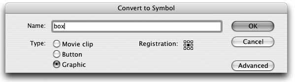
Choose Modify â Convert to Symbol (F8). This opens the Convert to Symbol dialog box, shown in Figure 1-13. In the Name field, type the word
box.For the Behavior type, choose Graphic. A graphic symbol is typically thought of as a type of animation that can be played in three ways without requiring any ActionScript: using the Properties panel, you can set a graphic symbol to loop, play once, or display a specific frame. Because they require no ActionScript, using graphics is a convenient way to start learning about symbols.
Note
If you create a graphic symbol with an animation inside it, the symbol must span the same number of frames in the main timeline that the graphic itself contains. For example, if a graphic symbol contains a 10-frame animation, the graphic must span 10 frames in the main timeline. If the symbol spans only five frames in the main timeline, the animation inside the graphic will only play to its midpoint.
Click OK to close the dialog box. You should see a blue line around the box you just drew. This indicates that the art is no longer a shape. In this case, it is now a symbol.
Itâs important to understand that a grouped image is not the same as a symbol. A grouped image is raw graphic data on the Stage, whereas a symbol is the defined blueprint for one or more instances of the same asset. If you made a copy of a group, you would literally be copying the vector data required to draw that group and, therefore, measurably increasing the file size. If you made a copy of a symbol instance, on the other hand, you would essentially be creating another reference to the single symbol residing in the Library. As youâll see next, the duplicated instance contributes negligibly to the size of your file.
Now that you have a symbol, you can reuse it as many times as you want without re-creating the drawing or adding significantly to the file size of the project:
The Library
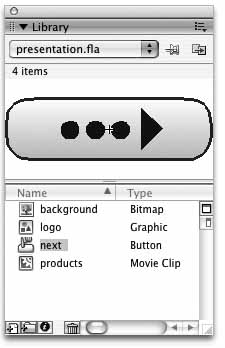
Every Flash file has its own Library, which serves as a repository for many of the fileâs assets. You can open the Library panel (shown in Figure 1-14) using Window â Library, Ctrl-L (Win), or Cmd-L (Mac). When you import an asset, such as a JPG file, it is accessible from the Library. The same is true for sounds, video clips, and similar assets. The Library also holds all symbols, which you will continue to learn about in future chapters.
The Library can help you organize your internal assets by enabling you to collect them into folders; rename, edit, update, and delete them; view thumbnails; set symbol properties; and more. Libraries can be shared among multiple published SWFs, and you can easily copy a specific Library element from one Flash file to another.
In fact, Flash 8 now collects the Libraries of all open documents into one panel, making it easier than ever before to move between them. You can create multiple Library panels for simplified dragging and dropping, and you can pin a Library to a file so that focusing on that file will also switch to the pinned Library.
Youâll be using the Library panel often, so take some time to get used to it and understand its features. In Chapter 5, youâll take a closer look at the Library and how to organize it effectively. Finally, be sure not to confuse an internal Flash Library with, say, a collection of ActionScript files, which may also be referred to colloquially as a library (as in âa library of scriptsâ)!
Currently, you have a single instance of a graphic symbol on the Stage. To begin, test your movie using the Control â Test Movie menu option. This will publish your file to a SWF and open it in a Preview window so you can check your progress. Right now, you just have a box sitting there doing nothing.
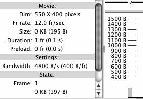
With the Preview window open, choose View â Bandwidth Profiler. This utility, seen in Figure 1-15, shows you how much bandwidth your movie is using at any given time and can help you optimize your files. The third line down displays the file size of your movie. It should say something close to â0 KB (120 B)â, but this may vary slightly. This means your movie is approximately 1/10th of 1 KB (kilobyte). Thatâs very small, which is good because a smaller file size means that less time will be spent waiting for your file to download.
Close the Preview window. Now itâs time to see how much the file size will be augmented by several additional instances of the symbol.
Drag the box symbol from the Library 10 more times. (It doesnât matter what your file looks like, as you are only testing file size in this exercise.)
Test the movie again (using Control â Test Movie). In the test case from which this exercise was derived, the movie size read â0 KB (190 B),â indicating that increasing the number of on-Stage symbol instances by 10 times added only 70 bytes to the file size. In fact, because of economies of scale you would need to add approximately 400 on-Stage instances of the symbol before the file grew larger than even 1 KB!
Close this file, but donât bother saving it. You wonât need it again.
You may notice that many Flash terms and concepts, such as âthe Stageâ and âmovie,â were borrowed from the film industry. Using a filmmaking metaphor can help you grasp many Flash concepts. For example, much like in a film, anything that appears on the Stage appears in the finished movie. A graphic that resides off-Stage is not seen in the final movie unless it moves onto the Stage at some point. To help cement this analogy, think about what other aspects of Flash development might be similar to filmmaking. (Hint: Look back over the section on symbols and instances.)
If you want to experiment some more before moving on to the next chapter, try editing the two stars you created earlier. To edit drawing objects, use the same technique you used for editing groups. Double-click each star, and the rest of the Stage will dim, allowing you to focus on editing the drawing object in place. Experiment by selecting the star, clicking on the fill color swatch, and changing the white fillâs Alpha value to 50% in the pop-up color palette.
Next, try cutting a star out of the background by breaking it apart, selecting it, and deleting it. (By breaking apart the drawing object, youâre allowing it to merge with the underlying background shape.) Finally, try something totally new: finish off the Hendrix poster image by adding some text with the Text tool.
With your new knowledge of the basic drawing tools in Flash, you can start drawing everything from cartoon characters and backgrounds to logos and layoutsâso get to it! This book is all about playing around, so have some fun.
In the next chapter, youâll learn how to make creating Flash magic quicker and easier by customizing your workspace. Youâll focus on:
How to create your own panel layout
How to change document settings
Several ways to align objects on the Stage
How to automate simple production tasks
Get Flash 8: Projects for Learning Animation and Interactivity now with the O’Reilly learning platform.
O’Reilly members experience books, live events, courses curated by job role, and more from O’Reilly and nearly 200 top publishers.

