Ethernet switches link Ethernet devices together by relaying Ethernet frames between the devices connected to the switches. By moving Ethernet frames between the switch ports, a switch links the traffic carried by the individual network connections into a larger Ethernet network.
Ethernet switches perform their linking function by bridging Ethernet frames between Ethernet segments. To do this, they copy Ethernet frames from one switch port to another, based on the Media Access Control (MAC) addresses in the Ethernet frames. Ethernet bridging was initially defined in the 802.1D IEEE Standard for Local and Metropolitan Area Networks: Media Access Control (MAC) Bridges.[1]
The standardization of bridging operations in switches makes it possible to buy switches from different vendors that will work together when combined in a network design. That’s the result of lots of hard work on the part of the standards engineers to define a set of standards that vendors could agree upon and implement in their switch designs.
The first Ethernet bridges were two-port devices that could link two of the original Ethernet system’s coaxial cable segments together. At that time, Ethernet only supported connections to coaxial cables. Later, when twisted-pair Ethernet was developed and switches with many ports became widely available, they were often used as the central connection point, or hub, of Ethernet cabling systems, resulting in the name “switching hub.” Today, in the marketplace, these devices are simply called switches.
Things have changed quite a lot since Ethernet bridges were first developed in the early 1980s. Over the years, computers have become ubiquitous, and many people use multiple devices at their jobs, including their laptops, smartphones, and tablets. Every VoIP telephone and every printer is a computer, and even building management systems and access controls (door locks) are networked. Modern buildings have multiple wireless access points (APs) to provide 802.11 Wi-Fi services for things like smartphones and tablets, and each of the APs is also connected to a cabled Ethernet system. As a result, modern Ethernet networks may consist of hundreds of switch connections in a building, and thousands of switch connections across a campus network.
You should know that there is another network device used to link networks, called a router. There are major differences in the ways that bridges and routers work, and they both have advantages and disadvantages, as described in Routers or Bridges?. Very briefly, bridges move frames between Ethernet segments based on Ethernet addresses with little or no configuration of the bridge required. Routers move packets between networks based on high-level protocol addresses, and each network being linked must be configured into the router. However, both bridges and routers are used to build larger networks, and both devices are called switches in the marketplace.
Tip
We will use the words “bridge” and “switch” interchangeably to describe Ethernet bridges. However, note that “switch” is a generic term for network devices that may function as bridges, or routers, or even both, depending on their feature sets and configuration. The point is that as far as network experts are concerned, bridging and routing are different kinds of packet switching with different capabilities. For our purposes, we will follow the practices of Ethernet vendors who use the word “switch,” or more specifically, “Ethernet switch,” to describe devices that bridge Ethernet frames.
While the 802.1D standard provides the specifications for bridging local area network frames between ports of a switch, and for a few other aspects of basic bridge operation, the standard is also careful to avoid specifying issues like bridge or switch performance or how switches should be built. Instead, vendors compete with one another to provide switches at multiple price points and with multiple levels of performance and capabilities.
The result has been a large and competitive market in Ethernet switches, increasing the number of choices you have as a customer. The wide range of switch models and capabilities can be confusing. In Chapter 4, we discuss special purpose switches and their uses.
Networks exist to move data between computers. To perform that task, the network software organizes the data being moved into Ethernet frames. Frames travel over Ethernet networks, and the data field of a frame is used to carry data between computers. Frames are nothing more than arbitrary sequences of information whose format is defined in a standard.
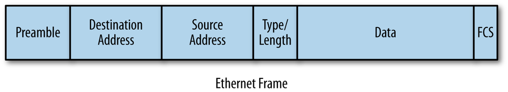
The format for an Ethernet frame includes a destination address at the beginning, containing the address of the device to which the frame is being sent.[2] Next comes a source address, containing the address of the device sending the frame. The addresses are followed by various other fields, including the data field that carries the data being sent between computers, as shown in Figure 1-1.
Frames are defined at Layer 2, or the Data Link Layer, of the Open Systems Interconnection (OSI) seven-layer network model. The seven-layer model was developed to organize the kinds of information sent between computers. It is used to define how that information will be sent and to structure the development of standards for transferring information. Since Ethernet switches operate on local area network frames at the Data Link Layer, you will sometimes hear them called link layer devices, as well as Layer 2 devices or Layer 2 switches.[3]
Ethernet switches are designed so that their operations are invisible to the devices on the network, which explains why this approach to linking networks is also called transparent bridging. “Transparent” means that when you connect a switch to an Ethernet system, no changes are made in the Ethernet frames that are bridged. The switch will automatically begin working without requiring any configuration on the switch or any changes on the part of the computers connected to the Ethernet network, making the operation of the switch transparent to them.
Next, we will look at the basic functions used in a bridge to make it possible to forward Ethernet frames from one port to another.
An Ethernet switch controls the transmission of frames between switch ports connected to Ethernet cables using the traffic forwarding rules described in the IEEE 802.1D bridging standard. Traffic forwarding is based on address learning. Switches make traffic forwarding decisions based on the 48-bit media access control (MAC) addresses used in LAN standards, including Ethernet.
To do this, the switch learns which devices, called stations in the standard, are on which segments of the network by looking at the source addresses in all of the frames it receives. When an Ethernet device sends a frame, it puts two addresses in the frame. These two addresses are the destination address of the device it is sending the frame to, and the source address, which is the address of the device sending the frame.
The way the switch “learns” is fairly simple. Like all Ethernet interfaces, every port on a switch has a unique factory-assigned MAC address. However, unlike a normal Ethernet device that accepts only frames addressed directed to it, the Ethernet interface located in each port of a switch runs in promiscuous mode. In this mode, the interface is programmed to receive all frames it sees on that port, not just the frames that are being sent to the MAC address of the Ethernet interface on that switch port.
As each frame is received on each port, the switching software looks at the source address of the frame and adds that source address to a table of addresses that the switch maintains. This is how the switch automatically discovers which stations are reachable on which ports.
Figure 1-2 shows a switch linking six Ethernet devices. For convenience, we’re using short numbers for station addresses, instead of actual 6-byte MAC addresses. As stations send traffic, the switch receives every frame sent and builds a table, more formally called a forwarding database, that shows which stations can be reached on which ports. After every station has transmitted at least one frame, the switch will end up with a forwarding database such as that shown in Table 1-1.
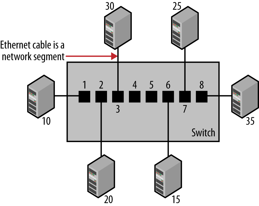
Table 1-1. Forwarding database maintained by a switch
| Port | Station |
|---|---|
1 | 10 |
2 | 20 |
3 | 30 |
4 | No station |
5 | No station |
6 | 15 |
7 | 25 |
8 | 35 |
This database is used by the switch to make a packet forwarding decision in a process called adaptive filtering. Without an address database, the switch would have to send traffic received on any given port out all other ports to ensure that it reached its destination. With the address database, the traffic is filtered according to its destination. The switch is “adaptive” by learning new addresses automatically. This ability to learn makes it possible for you to add new stations to your network without having to manually configure the switch to know about the new stations, or the stations to know about the switch.[4]
When the switch receives a frame that is destined for a station address that it hasn’t yet seen, the switch will send the frame out all of the ports other than the port on which it arrived.[5] This process is called flooding, and is explained in more detail later in Frame Flooding.
Once the switch has built a database of addresses, it has all the information it needs to filter and forward traffic selectively. While the switch is learning addresses, it is also checking each frame to make a packet forwarding decision based on the destination address in the frame. Let’s look at how the forwarding decision works in a switch equipped with eight ports, as shown in Figure 1-2.
Assume that a frame is sent from station 15 to station 20. Since the frame is sent by station 15, the switch reads the frame in on port 6 and uses its address database to determine which of its ports is associated with the destination address in this frame. Here, the destination address corresponds to station 20, and the address database shows that to reach station 20, the frame must be sent out port 2.
Each port in the switch has the ability to hold frames in memory, before transmitting them onto the Ethernet cable connected to the port. For example, if the port is already busy transmitting when a frame arrives for transmission, then the frame can be held for the short time it takes for the port to complete transmitting the previous frame. To transmit the frame, the switch places the frame into the packet switching queue for transmission on port 2.
During this process, a switch transmitting an Ethernet frame from one port to another makes no changes to the data, addresses, or other fields of the basic Ethernet frame. Using our example, the frame is transmitted intact on port 2 exactly as it was received on port 6. Therefore, the operation of the switch is transparent to all stations on the network.
Note that the switch will not forward a frame destined for a station that is in the forwarding database onto a port unless that port is connected to the target destination. In other words, traffic destined for a device on a given port will only be sent to that port; no other ports will see the traffic intended for that device. This switching logic keeps traffic isolated to only those Ethernet cables, or segments, needed to receive the frame from the sender and transmit that frame to the destination device.
This prevents the flow of unnecessary traffic on other segments of the network system, which is a major advantage of a switch. This is in contrast to the early Ethernet system, where traffic from any station was seen by all other stations, whether they wanted the data or not. Switch traffic filtering reduces the traffic load carried by the set of Ethernet cables connected to the switch, thereby making more efficient use of the network bandwidth.
Switches automatically age out entries in their forwarding database after a period of time—typically five minutes—if they do not see any frames from a station. Therefore, if a station doesn’t send traffic for a designated period, then the switch will delete the forwarding entry for that station. This keeps the forwarding database from growing full of stale entries that might not reflect reality.
Of course, once the address entry has timed out, the switch won’t have any information in the database for that station the next time the switch receives a frame destined for it. This also happens when a station is newly connected to a switch, or when a station has been powered off and is turned back on more than five minutes later. So how does the switch handle packet forwarding for an unknown station?
The solution is simple: the switch forwards the frame destined for an unknown station out all switch ports other than the one it was received on, thus flooding the frame to all other stations. Flooding the frame guarantees that a frame with an unknown destination address will reach all network connections and be heard by the correct destination device, assuming that it is active and on the network. When the unknown device responds with return traffic, the switch will automatically learn which port the device is on, and will no longer flood traffic destined to that device.
In addition to transmitting frames directed to a single address, local area networks are capable of sending frames directed to a group address, called a multicast address, which can be received by a group of stations. They can also send frames directed to all stations, using the broadcast address. Group addresses always begin with a specific bit pattern defined in the Ethernet standard, making it possible for a switch to determine which frames are destined for a specific device rather than a group of devices.
A frame sent to a multicast destination address can be received by all stations configured to listen for that multicast address. The Ethernet software, also called “interface driver” software, programs the interface to accept frames sent to the group address, so that the interface is now a member of that group. The Ethernet interface address assigned at the factory is called a unicast address, and any given Ethernet interface can receive unicast frames and multicast frames. In other words, the interface can be programmed to receive frames sent to one or more multicast group addresses, as well as frames sent to the unicast MAC address belonging to that interface.
The broadcast address is a special multicast group: the group of all of the stations in the network. A packet sent to the broadcast address (the address of all 1s) is received by every station on the LAN. Since broadcast packets must be received by all stations on the network, the switch will achieve that goal by flooding broadcast packets out all ports except the port that it was received on, since there’s no need to send the packet back to the originating device. This way, a broadcast packet sent by any station will reach all other stations on the LAN.
Multicast traffic can be more difficult to deal with than broadcast frames. More sophisticated (and usually more expensive) switches include support for multicast group discovery protocols that make it possible for each station to tell the switch about the multicast group addresses that it wants to hear, so the switch will send the multicast packets only to the ports connected to stations that have indicated their interest in receiving the multicast traffic. However, lower cost switches, with no capability to discover which ports are connected to stations listening to a given multicast address, must resort to flooding multicast packets out all ports other than the port on which the multicast traffic was received, just like broadcast packets.
Stations send broadcast and multicast packets for a number of reasons. High-level network protocols like TCP/IP use broadcast or multicast frames as part of their address discovery process. Broadcasts and multicasts are also used for dynamic address assignment, which occurs when a station is first powered on and needs to find a high-level network address. Multicasts are also used by certain multimedia applications, which send audio and video data in multicast frames for reception by groups of stations, and by multi-user games as a way of sending data to a group of game players.
Therefore, a typical network will have some level of broadcast and multicast traffic. As long as the number of such frames remains at a reasonable level, then there won’t be any problems. However, when many stations are combined by switches into a single large network, broadcast and multicast flooding by the switches can result in significant amounts of traffic. Large amounts of broadcast or multicast traffic may cause network congestion, since every device on the network is required to receive and process broadcasts and specific types of multicasts; at high enough packet rates, there could be performance issues for the stations.
Streaming applications (video) sending high rates of multicasts can generate intense traffic. Disk backup and disk duplication systems based on multicast can also generate lots of traffic. If this traffic ends up being flooded to all ports, the network could congest. One way to avoid this congestion is to limit the total number of stations linked to a single network, so that the broadcast and multicast rate does not get so high as to be a problem.
Another way to limit the rate of multicast and broadcast packets is to divide the network into multiple virtual LANs (VLANs). Yet another method is to use a router, also called a Layer 3 switch. Since a router does not automatically forward broadcasts and multicasts, this creates separate network systems.[6] These methods for controlling the propagation of multicasts and broadcasts are discussed in Chapter 2 and Chapter 3, respectively.
So far we’ve seen how a single switch can forward traffic based on a dynamically-created forwarding database. A major difficulty with this simple model of switch operation is that multiple connections between switches can create loop paths, leading to network congestion and overload.
The design and operation of Ethernet requires that only a single packet transmission path may exist between any two stations. An Ethernet grows by extending branches in a network topology called a tree structure, which consists of multiple switches branching off of a central switch. The danger is that, in a sufficiently complex network, switches with multiple inter-switch connections can create loop paths in the network.
On a network with switches connected together to form a packet forwarding loop, packets will circulate endlessly around the loop, building up to very high levels of traffic and causing an overload.
The looped packets will circulate at the maximum rate of the network links, until the traffic rate gets so high that the network is saturated. Broadcast and multicast frames, as well as unicast frames to unknown destinations, are normally flooded to all ports in a basic switch, and all of this traffic will circulate in such a loop. Once a loop is formed, this failure mode can happen very rapidly, causing the network to be fully occupied with sending broadcast, multicast, and unknown frames, and it becomes very difficult for stations to send actual traffic.
Unfortunately, loops like the dotted path shown with arrows in Figure 1-3 are all too easy to achieve, despite your best efforts to avoid them. As networks grow to include more switches and more wiring closets, it becomes difficult to know exactly how things are connected together and to keep people from mistakenly creating a loop path.
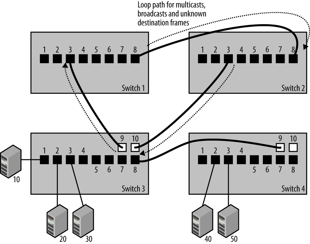
While the loop in the drawing is intended to be obvious, in a sufficiently complex network system it can be challenging for anyone working on the network to know whether or not the switches are connected in such a way as to create loop paths. The IEEE 802.1D bridging standard provides a spanning tree protocol to avoid this problem by automatically suppressing forwarding loops.
The purpose of the spanning tree protocol (STP) is to allow switches to automatically create a loop-free set of paths, even in a complex network with multiple paths connecting multiple switches. It provides the ability to dynamically create a tree topology in a network by blocking any packet forwarding on certain ports, and ensures that a set of Ethernet switches can automatically configure themselves to produce loop-free paths. The IEEE 802.1D standard describes the operation of spanning tree, and every switch that claims compliance with the 802.1D standard must include spanning tree capability.[7]
Operation of the spanning tree algorithm is based on configuration messages sent by each switch in packets called Bridge Protocol Data Units, or BPDUs. Each BPDU packet is sent to a destination multicast address that has been assigned to spanning tree operation. All IEEE 802.1D switches join the BPDU multicast group and listen to frames sent to this address, so that every switch can send and receive spanning tree configuration messages.[8]
The process of creating a spanning tree begins by using the information in the BPDU configuration messages to automatically elect a root bridge. The election is based on a bridge ID (BID) which, in turn, is based on the combination of a configurable bridge priority value (32,768 by default) and the unique Ethernet MAC address assigned on each bridge for use by the spanning tree process, called the system MAC. Bridges send BPDUs to one another, and the bridge with the lowest BID is automatically elected to be the root bridge.
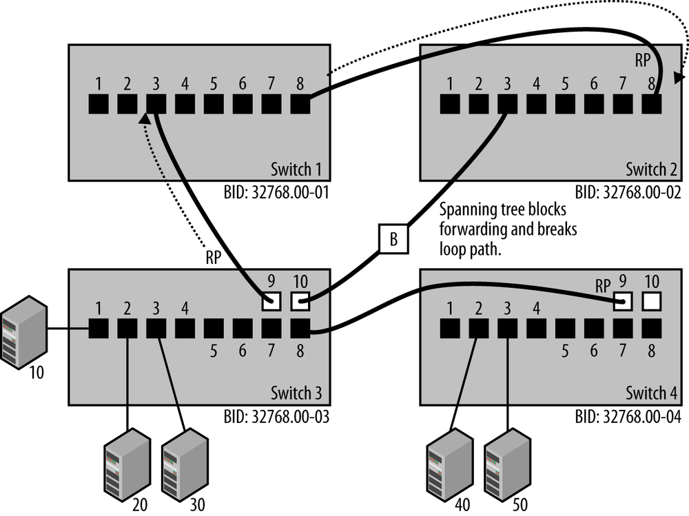
Assuming that the bridge priority was left at the default value of 32,768, then the bridge with the lowest numerical value Ethernet address will be the one elected as the root bridge.[9] In the example shown in Figure 1-4, Switch 1 has the lowest BID, and the end result of the spanning tree election process is that Switch 1 has become the root bridge. Electing the root bridge sets the stage for the rest of the operations performed by the spanning tree protocol.
Once a root bridge is chosen, each non-root bridge uses that information to determine which of its ports has the least-cost path to the root bridge, then assigns that port to be the root port (RP). All other bridges determine which of their ports connected to other links has the least-cost path to the root bridge. The bridge with the least-cost path is assigned the role of designated bridge (DB), and the ports on the DB are assigned as designated ports (DP).
The path cost is based on the speed at which the ports operate, with higher speeds resulting in lower costs. As BPDU packets travel through the system, they accumulate information about the number of ports they travel through and the speed of each port. Paths with slower speed ports will have higher costs. The total cost of a given path through multiple switches is the sum of the costs of all the ports on that path.
Tip
If there are multiple paths to the root with the same cost, then the path connected to the bridge with the lowest bridge ID will be used.
At the end of this process, the bridges have chosen a set of root ports and designated ports, making it possible for the bridges to remove all loop paths and maintain a packet forwarding tree that spans the entire set of devices connected to the network, hence the name “spanning tree protocol.”
Once the spanning tree process has determined the port status, then the combination of root ports and designated ports provides the spanning tree algorithm with the information it needs to identify the best paths and block all other paths. Packet forwarding on any port that is not a root port or a designated port is disabled by blocking the forwarding of packets on that port.
While blocked ports do not forward packets, they continue to receive BPDUs. The blocked port is shown in Figure 1-4 with a “B,” indicating that port 10 on Switch 3 is in blocking mode and that the link is not forwarding packets. The Rapid Spanning Tree Protocol (RSTP) sends BPDU packets every two seconds to monitor the state of the network, and a blocked port may become unblocked when a path change is detected.
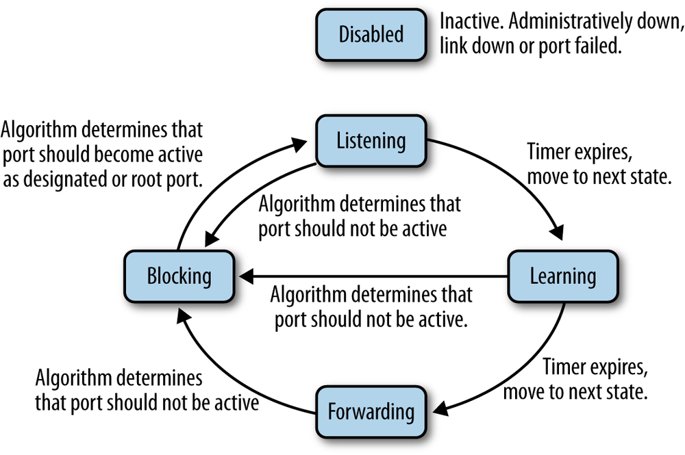
When an active device is connected to a switch port, the port goes through a number of states as it processes any BPDUs that it might receive, and the spanning tree process determines what state the port should be in at any given time. Two of the states are called listening and learning, during which the spanning tree process listens for BPDUs and also learns source addresses from any frames received.
Figure 1-5 shows the spanning tree port states, which include the following:
- Disabled
- A port in this state has been intentionally shut down by an administrator, or has automatically shut down because the link was disconnected. This also could be a port that has failed, and is no longer operational. The Disabled state can be entered or exited from any other state.
- Blocking
- A port that is enabled, but is not a root port or designated port could cause a switching loop if it were active. To avoid that, the port is placed in the blocking state. No station data is sent or received over a blocking port. Upon initialization of a port (link comes up, power is turned on), the port will typically enter the blocking state. Upon discovering via BPDUs or timeouts that the port may need to become active, the port will move to the listening state on the way to the forwarding state. A blocking port may also transition to the forwarding state if other links fail. BPDU data is still received while a port is in the blocking state.
- Listening
- In this state, the port discards traffic but continues to process BPDUs received on the port, and acts on any new information that would cause the port to return to the blocked state. Based on information received in BPDUs, the port may transition to the learning state. The listening state allows the spanning tree algorithm to decide whether the attributes of this port, such as port cost, would cause the port to become part of the spanning tree or return to the blocking state.
- Learning
- In this state, the port does not yet forward frames, but it does learn source addresses from any frames received and adds them to the filtering database. The switch will populate the MAC address table with packets heard on the port (until the timer expires), before moving to the forwarding state.
- Forwarding
- This is the operational state in which a port sends and receives station data. Incoming BPDUs are also monitored to allow the bridge to detect if it needs to move the port into the blocking state to prevent a loop.
In the original spanning tree protocol, the listening and learning states lasted for 30 seconds, during which time packets were not forwarded. In the newer Rapid Spanning Tree Protocol, it is possible to assign a port type of “edge” to a port, meaning that the port is known to be connected to an end station (user computer, VoIP telephone, printer, etc.) and not to another switch. That allows the RSTP state machine to bypass the learning and listening processes on that port and to transition to the forwarding state immediately. Allowing a station to immediately begin sending and receiving packets helps avoid such issues as application timeouts on user computers when they are rebooted.[10] While not required for RSTP operation, it is useful to manually configure RSTP edge ports with their port type, to avoid issues on user computers. Setting the port type to edge also means that RSTP doesn’t need to send a BPDU packet upon link state change (link up or down) on that port, which helps reduce the amount of spanning tree traffic in the network.
Tip
The inventor of the spanning tree protocol, Radia Perlman, wrote a poem to describe how it works.[11] When reading the poem it helps to know that in math terms, a network can be represented as a type of graph called a mesh, and that the goal of the spanning tree protocol is to turn any given network mesh into a tree structure with no loops that spans the entire set of network segments.
I think that I shall never see
A graph more lovely than a tree.
A tree whose crucial property
Is loop-free connectivity.
A tree that must be sure to span
So packets can reach every LAN.
First, the root must be selected.
By ID, it is elected.
Least cost paths from root are traced.
In the tree, these paths are placed.
A mesh is made by folks like me,
Then bridges find a spanning tree.— Radia Perlman Algorhyme
This brief description is only intended to provide the basic concepts behind the operation of the system. As you might expect, there are more details and complexities that are not described. The complete details of how the spanning tree state machine operates are described in the IEEE 802.1 standards, which can be consulted for a more complete understanding of the protocol and how it functions. The details of vendor-specific spanning tree enhancements can be found in the vendor documentation. See Appendix A for links to further information.
The original spanning tree protocol, standardized in IEEE 802.1D, specified a single spanning tree process running on a switch, managing all ports and VLANs with a single spanning tree state machine. Nothing in the standard prohibits a vendor from developing their own enhancements to how spanning tree is deployed. Some vendors created their own implementations, in one case providing a separate spanning tree process per VLAN. That approach was taken by Cisco Systems for a version they call per-VLAN spanning tree (PVST).
The IEEE standard spanning tree protocol has evolved over the years. An updated version, called the Rapid Spanning Tree Protocol, was defined in 2004. As the name implies, Rapid Spanning Tree has increased the speed at which the protocol operates. RSTP was designed to provide backward compatibility with the original version of spanning tree. The 802.1Q standard includes both RSTP and a new version of spanning tree called Multiple Spanning Tree (MST), which is also designed to provide backward compatibility with previous versions.[12] MST is discussed further in Virtual LANs.
When building a network with multiple switches, you need to pay careful attention to how the vendor of your switches has deployed spanning tree, and to the version of spanning tree your switches use. The most commonly used versions, classic STP and the newer RSTP, are interoperable and require no configuration, resulting in “plug and play” operation.
Before putting a new switch into operation on your network, read the vendor’s documentation carefully and make sure that you understand how things work. Some vendors may not enable spanning tree as a default on all ports. Other vendors may implement special features or vendor-specific versions of spanning tree. Typically, a vendor will work hard to make sure that their implementation of spanning tree “just works” with all other switches, but there are enough variations in spanning tree features and configuration that you may encounter issues. Reading the documentation and testing new switches before deploying them throughout your network can help avoid any problems.
A single full-duplex Ethernet connection is designed to move Ethernet frames between the Ethernet interfaces at each end of the connection. It operates at a known bit rate and a known maximum frame rate.[13] All Ethernet connections at a given speed will have the same bit rate and frame rate characteristics. However, adding switches to the network creates a more complex system. Now, the performance limits of your network become a combination of the performance of the Ethernet connections and the performance of the switches, as well as of any congestion that may occur in the system, depending on topology. It’s up to you to make sure that the switches you buy have enough performance to do the job.
The performance of the internal switching electronics may not be able to sustain the full frame rate coming in from all ports. In other words, should all ports simultaneously present high traffic loads to the switch that are also continual and not just short bursts, the switch may not be able to handle the combined traffic rate and may begin dropping frames. This is known as blocking, the condition in a switching system in which there are insufficient resources available to provide for the flow of data through the switch. A non-blocking switch is one that provides enough internal switching capability to handle the full load even when all ports are simultaneously active for long periods of time. However, even a non-blocking switch will discard frames when a port becomes congested, depending on traffic patterns.
Typical switch hardware has dedicated support circuits that are designed to help improve the speed with which the switch can forward a frame and perform such essential functions as looking up frame addresses in the address filtering database. Because support circuits and high-speed buffer memory are more expensive components, the total performance of a switch is a trade-off between the cost of those high performance components and the price most customers are willing to pay. Therefore, you will find that not all switches perform alike.
Some less expensive devices may have lower packet forwarding performance, smaller address filtering tables, and smaller buffer memories. Larger switches with more ports will typically have higher performance components and a higher price tag. Switches capable of handling the maximum frame rate on all of their ports, also described as non-blocking switches, are capable of operating at wire speed. Fully non-blocking switches that can handle the maximum bit rate simultaneously on all ports are common these days, but it’s always a good idea to check the specifications for the switch you are considering.
The performance required and the cost of the switches you purchase can vary depending on their location in the network. The switches you use in the core of a network need to have enough resources to handle high traffic loads. That’s because the core of the network is where the traffic from all stations on the network converges. Core switches need to have the resources to handle multiple conversations, high traffic loads, and long duration traffic. On the other hand, the switches used at the edges of a network can be lower performance, since they are only required to handle the traffic loads of the directly connected stations.
All switches contain some high-speed buffer memory in which a frame is stored, however briefly, before being forwarded onto another port or ports of the switch. This mechanism is known as store-and-forward switching. All IEEE 802.1D-compliant switches operate in store-and-forward mode, in which the packet is fully received on a port and placed into high-speed port buffer memory (stored) before being forwarded. A larger amount of buffer memory allows a bridge to handle longer streams of back-to-back frames, giving the switch improved performance in the presence of bursts of traffic on the LAN. A common switch design includes a pool of high-speed buffer memory that can be dynamically allocated to individual switch ports as needed.
Given that a switch is a special-purpose computer, the central CPU and RAM in a switch are important for such functions as spanning tree operations, providing management information, managing multicast packet flows, and managing switch port and feature configuration.
As usual in the computer industry, the more CPU performance and RAM, the better, but you will pay more as well. Vendors frequently do not make it easy for customers to find switch CPU and RAM specifications. Typically, higher cost switches will make this information available, but you won’t be able to order a faster CPU or more RAM for a given switch. Instead, this is information useful for comparing models from a vendor, or among vendors, to see which switches have the best specifications.
Switch performance includes a range of metrics, including the maximum bandwidth, or switching capacity of the packet switch electronics, inside the switch. You should also see the maximum number of MAC addresses that the address database can hold, as well as the maximum rate in packets per second that the switch can forward on the combined set of ports.
Shown here is a set of switch specifications copied from a typical vendor’s data sheet. The vendor’s specifications are shown in bold type. To keep things simple, in our example we show the specifications for a small, low-cost switch with five ports. This is intended to show you some typical switch values, and also to help you understand what the values mean and what happens when marketing and specifications meet on a single page.
- Forwarding
- Store-and-forward
- Refers to standard 802.1D bridging, in which a packet is completely received on a port and into the port buffer (“store”) before being forwarded.
- 128 KB on-chip packet buffering
- The total amount of packet buffering available to all ports. The buffering is shared between the ports on an on-demand basis. This is a typical level of buffering for a small, light-duty, five-port switch intended to support client connections in a home office.
Tip
Some switches designed for use in data centers and other specialized networks support a mode of operation called cut-through switching, in which the packet forwarding process begins before the entire packet is read into buffer memory. The goal is to reduce the time required to forward a packet through the switch. This method also forwards packets with errors, since it begins forwarding a packet before the error checking field is received.
- Performance
- Bandwidth: 10 Gb/s (non-blocking)
- Since this switch can handle the full traffic load across all ports operating at maximum traffic rate on each port, it is a non-blocking switch. The five ports can operate up to 1 Gb/s each. In full-duplex mode, the maximum rate through the switch, with all ports active, is 5 Gb/s in the outbound direction (also called “egress”) and 5 Gb/s in the inbound direction (also called “ingress”). Vendors like to list a total of 10 Gb/s aggregate bandwidth on their specifications, although the 5 Gb/s of ingress data on five ports is being sent as 5 Gb/s of egress data. If you regarded the maximum aggregate data transfer through the switch as 5 Gb/s, you would be technically correct, but you would not succeed in marketing.[14]
- Forwarding rate
-
10 Mbps port: 14,800 packets/sec
100 Mbps port: 148,800 packets/sec
1000 Mbps port: 1,480,000 packets/sec - These specifications show that the ports can handle the full packet switching rate consisting of minimum-sized Ethernet frames (64 bytes), which is as fast as the packet rate can go at the smallest frame size. Larger frames will have a lower packet rate per second, so this is the peak performance specification for an Ethernet switch. This shows that the switch can support the maximum packet rate on all ports at all supported speeds.
-
10 Mbps port: 14,800 packets/sec
- Latency (using 1500-byte packets)
-
10 Mbps: 30 microseconds (max)
100 Mbps: 6 microseconds (max)
1000 Mbps: 4 microseconds (max) - This is the amount of time it takes to move an Ethernet frame from the receiving port to the transmitting port, assuming that the transmitting port is available and not busy transmitting some other frame. It is a measure of the internal switching delay imposed by the switch electronics. This measurement is also shown as 30 µs, using the Greek “mu” character to indicate “micro.” A microsecond is one millionth of a second, and 30 millionths of a second latency on 10Mbps ports is a reasonable value for a low-cost switch. When comparing switches, a lower value is better. More expensive switches typically provide lower latency.
-
10 Mbps: 30 microseconds (max)
- MAC address database: 4,000
- This switch can support up to 4,000 unique station addresses in its address database. This is more than enough for a five-port switch intended for home office and small office use.
- Mean time between failures
- (MTBF): >1 million hours (~114 years) The MTBF is high because this switch is small, has no fan that can wear out, and has a low component count; there aren’t many elements that can fail. This doesn’t mean that the switch can’t fail, but there are few failures in these electronics, resulting in a large mean time between failures for this switch design.
- Standards compliance
-
IEEE 802.3i 10BASE-T Ethernet
IEEE 802.3u 100BASE-TX Fast Ethernet
IEEE 802.3ab 1000BASE-T Gigabit Ethernet
Honors IEEE 802.1p and DSCP priority tags
Jumbo frame: up to 9,720 bytes - Under the heading of “standards compliance” the vendor has provided a laundry list of the standards for which this switch can claim compliance. The first three items mean that the switch ports support twisted-pair Ethernet standards for 10/100/1000 Mbps speeds. These speeds are automatically selected while interacting with the client connection, using the Ethernet Auto-Negotiation protocol. Next, the vendor states that this switch will honor Class of Service priority tags on an Ethernet frame, by discarding traffic with lower-priority tags first in the event of port congestion. The last item in this laundry list notes that the switch can handle non-standard Ethernet frame sizes, often called “jumbo frames,” which are sometimes configured on the Ethernet interfaces for a specific group of clients and their server(s) in an attempt to improve performance.[15]
-
IEEE 802.3i 10BASE-T Ethernet
This set of vendor specifications shows you what port speeds the switch supports and gives you an idea of how well the switch will perform in your system. When buying larger and higher-performance switches intended for use in the core of a network, there are other switch specifications that you should consider. These include support for extra features like multicast management protocols, command line access to allow you to configure the switch, and the Simple Network Management Protocol to enable you to monitor the switch’s operation and performance.
When using switches, you need to keep your network traffic requirements in mind. For example, if your network includes high-performance clients that place demands on a single server or set of servers, then whatever switch you use must have enough internal switching performance, high enough port speeds and uplink speeds, and sufficient port buffers to handle the task. In general, the higher-cost switches with high-performance switching fabrics also have good buffering levels, but you need to read the specifications carefully and compare different vendors to ensure that you are getting the best switch for the job.
[1] The most recent version of the 802.1D bridging standard is dated 2004. The 802.1D standard was extended and enhanced by the subsequent development of the 802.1Q-2011 standard, “Media Access Control (MAC) Bridges and Virtual Bridge Local Area Networks.”
[2] The Preamble field at the beginning of the frame is automatically stripped off when the frame is received on an Ethernet interface, leaving the Destination Address as the first field.
[3] The TCP/IP network protocol is based on network layer packets. The TCP/IP packets are carried between computers in the data field of Ethernet frames. In essence, Ethernet functions as the trucking system that transports TCP/IP packets between computers, carried as data in the Ethernet frame. You will also hear Ethernet frames referred to as “packets,” but as far as the standards are concerned, Ethernet uses frames to carry data between computers.
[4] Any Ethernet system still using coaxial cable segments and/or repeater hubs may have multiple stations on a network segment. Connecting that segment to a switch will result in multiple stations being reachable over a single port.
[5] Suppressing frame transmission on the switch port prevents stations on a shared segment connected to that port from seeing the same traffic more than once. This also prevents a single station on a port from receiving a copy of the frame it just sent.
[6] Both Layer 3 networks and VLANs create separate broadcast domains. Broadcasts and link layer multicasts are not automatically forwarded between networks by routers, and each VLAN operates as a separate and distinct LAN. Therefore, both routers and VLANs provide separate broadcast domains that limit the propagation of broadcasts and multicasts in a complex network system.
[7] Beware that low-cost switches may not include spanning tree capability, rendering them unable to block any packet forwarding loops. Also, some vendors that provide spanning tree may disable it by default, requiring you to manually enable spanning tree before it will function to protect your network.
[8] The bridge multicast group MAC address is 01-80-C2-00-00-00. Vendor-specific spanning tree enhancements may also use other addresses. For example, Cisco per-VLAN spanning tree (PVST) sends BPDUs to address 01-00-0C-CC-CC-CD.
[9] It may happen that a low-performance bridge on your network will have the lowest MAC address and end up as the root bridge. You can configure a lower bridge priority on your core bridge to ensure that the core bridge is chosen to be the root, and that the root will be located at the core of your network and running on the higher-performance switch located there.
[10] Prior to the development of RSTP, some vendors had developed their own versions of this feature. Cisco Systems, for example, provided the “portfast” command to enable an edge port to immediately begin forwarding packets.
[11] Perlman, Radia. Interconnections: Bridges, Routers, Switches and Internetworking Protocols (2nd Edition), New York: Addison-Wesley, 1999, p. 46.
[12] The IEEE 802.1Q standard notes that: “The spanning tree protocols specified by this standard supersede the Spanning Tree Protocol (STP) specified in IEEE Std 802.1D revisions prior to 2004, but facilitate migration by interoperating with the latter…”
[13] For example, a 100 Mbps Ethernet LAN can send a maximum of 148,809 frames per second, when using the minimum frame size of 64 bytes.
[14] If switch vendors marketed automobiles, then presumably they would market a car with a speedometer topping out at 120 mph as being a vehicle that provides an aggregate speed of 480 mph, since each of the four wheels can reach 120 mph at the same time. This is known as “marketing math” in the network marketplace.
[15] Jumbo frames can be made to work locally for a specific set of machines that you manage and configure. However, the Internet consists of billions of Ethernet ports, all operating with the standard maximum frame size of 1,500 bytes. If you want things to work well over the Internet, stick with standard frame sizes.
Get Ethernet Switches now with the O’Reilly learning platform.
O’Reilly members experience books, live events, courses curated by job role, and more from O’Reilly and nearly 200 top publishers.

