3.1. Introduction
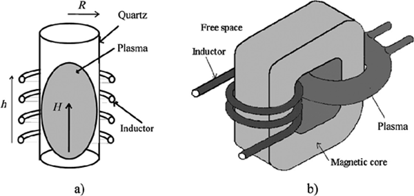
A thermal inductive plasma applicator is considered to be a transformer, with a solenoidal inductor as a primary and the electrically conductive plasma’s short-circuited coil as a secondary.
The plasma is contained in a cylindrical or annular enclosure (quartz or cold crucible).
The energy transfer toward the plasma in these applicators is done by couplings of various natures:
– The first coupling is done through air. It is more useful at high frequencies than low frequencies. It offers a mediocre coupling. In this type of applicator, the plasma is contained in a cylindrical enclosure. It is known as an “inductive plasma torch”.
– The second coupling is done through a closed magnetic core, ensuring a good coupling. This type of coupling has been used at very low frequency to heat metallic rings or crowns and acidic or basic liquids. In principle, it can be transposable (as will be shown) to the generation of voluminous inductive plasmas in annular configuration [ECK 71, MIM 96, SOL 00, ULA 10]. It is then known as a “plasma transformer” (Figure 3.1b).
Figure 3.1. Plasma torch and transformer

To increase the power in an inductive plasma torch, we must increase the frequency up to a few MHz and the generator’s voltage to a few kV. In an inductive plasma transformer, however, we can generate the same power with very low frequencies (VLF) of a few kHz and fairly ...
Get Electrothermics now with the O’Reilly learning platform.
O’Reilly members experience books, live events, courses curated by job role, and more from O’Reilly and nearly 200 top publishers.

