6.6 Asymmetric Stripline
In some layups, there are two trace layers between conducting planes. These trace layers are usually routed at right angles to each other to reduce capacitive cross coupling. The characteristic impedance of traces in one layer is not significantly affected by the crossing of traces on the second layer.
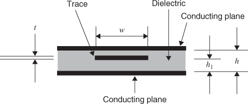
In some layups, a single trace layer is placed between conducting planes with a different dielectric thickness under and over the trace. The formula for the characteristic impedance is given by Equation 6.5. The conductor spacings for this configuration is given in Figure 6.12.
where h1 > h, 0.1 < w/h < 2, and t/h < 2.5.
Figure 6.12 Asymmetric stripline.
Get Digital Circuit Boards: Mach 1 GHz now with the O’Reilly learning platform.
O’Reilly members experience books, live events, courses curated by job role, and more from O’Reilly and nearly 200 top publishers.

