4.4 The Four-Terminal Capacitor or DTL
The most effective way to provide fast decoupling is to build the capacitor as a four-terminal transmission line. Energy is supplied from one end and taken from the other. In effect, this is a transmission line positioned between a load and a source of energy. We can call this a decoupling transmission line or DTL. The source impedance of this DTL determines the voltage drop when a demand is made for current. The length of the DTL determines how long this voltage is sustained. After a demand for current, the voltage drop depends on the ratio of characteristic impedances. A small wave makes a round trip in the DTL. When the wave returns to the load, the voltage will drop a second time. A loaded four-terminal capacitor is shown in Figure 4.3.
Figure 4.3 A four-terminal capacitor (DTL) in a circuit. The values shown are characteristic impedances.
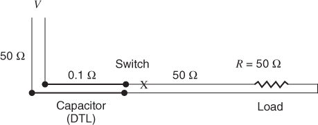
A practical DTL could have a source impedance as low as 0.1 ohm. A 1-A demand at the load end would cause a voltage drop of 0.1 V. When the resulting wave reaches the far end of the DTL, a wave is both reflected and transmitted depending on the parameters at the discontinuity. If the far end is a short transmission line connected to a voltage source then many round trips can take place in this short line before a second wave makes a round trip in the DTL. Section 2.15 discussed the flow of energy between ...
Get Digital Circuit Boards: Mach 1 GHz now with the O’Reilly learning platform.
O’Reilly members experience books, live events, courses curated by job role, and more from O’Reilly and nearly 200 top publishers.

