2.8 The Short Circuited Transmission Line
Consider the short circuited transmission line shown in Figures 2.6(a) and (b).
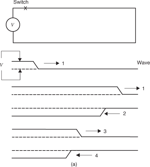
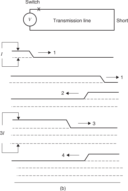
After the switch closes, a step wave (1) travels down the line to the right. At the short circuit, a reflected wave (2) starts back that cancels the voltage on the line. Poynting's vector on wave (2) requires that the E field must reverse polarity, but the H field polarity must not change. This means that the current flow on the line behind wave (2) is doubled. When wave (2) reaches the switch, it is again reflected. Poynting's vector for this reflected wave (3) requires that the E field be reversed and the H field again stays constant. Thus, the current in the line after the second reflection is three times the original current. The source supplies a current I until wave (2) returns to the source. After the second reflection, the source must supply 3I. Obviously, the process repeats itself after each pair of reflections. At the end of the fourth reflection, the voltage source must supply 5I. The current builds until the voltage source can no longer supply the current, the traces melt or a fuse blows.
A short circuit current develops through a series of wave reflections. The length ...
Get Digital Circuit Boards: Mach 1 GHz now with the O’Reilly learning platform.
O’Reilly members experience books, live events, courses curated by job role, and more from O’Reilly and nearly 200 top publishers.

