LOW-PASS/HIGH-PASS FILTER
The circuit of a low-pass/high-pass filter is shown in Fig 18.7. It consists of two RC networks connected in series with a buffer amplifier.
The adjustable frequency characteristics are shown in Fig. 18.8. The following frequency limits can be selected.
Lower frequency 40, 80, 160 and 270 Hz; upper frequency 11, 9, 4.5, 3.2 kHz.
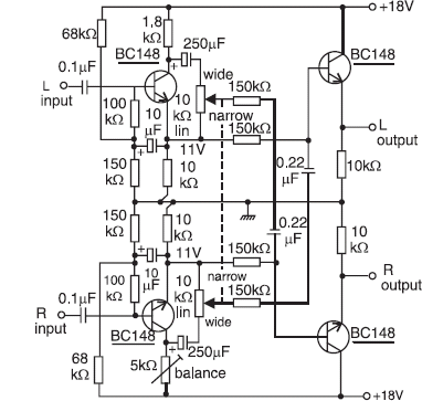
Fig. 18.6 Sound source width (dimension) control circuit
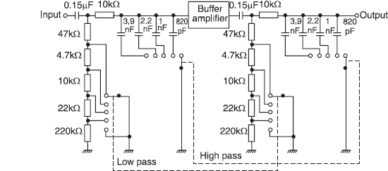
Fig. 18.7 Low-pass/high-pass filter circuit
Get Consumer Electronics now with the O’Reilly learning platform.
O’Reilly members experience books, live events, courses curated by job role, and more from O’Reilly and nearly 200 top publishers.

