Chapter 9. Capes
9.0 Introduction
Previous chapters of this book show a variety of ways to interface BeagleBone Black to the physical world by using a breadboard and wiring to the P8 and P9 headers. This is a great approach because itâs easy to modify your circuit to debug it or try new things. At some point, though, you might want a more permanent solution, either because you need to move the Bone and you donât want wires coming loose, or because you want to share your hardware with the masses.
You can easily expand the functionality of the Bone by adding a cape. A cape is simply a boardâoften a printed circuit board (PCB)âthat connects to the P8 and P9 headers and follows a few standard pin usages. You can stack up to four capes onto the Bone. Capes can range in size from Bone-sized (Recipe 9.2) to much larger than the Bone (Recipe 9.1).
This chapter shows how to attach a couple of capes, move your design to a protoboard, then to a PCB, and finally on to mass production.
9.1 Using a Seven-Inch LCD Cape
Problem
You want to display the Boneâs desktop on a portable LCD.
Solution
A number of LCD capes are built for the Bone, ranging in size from three to seven inches. This recipe attaches a seven-inch BeagleBone LCD7 from CircuitCo (shown in Figure 9-1) to the Bone.
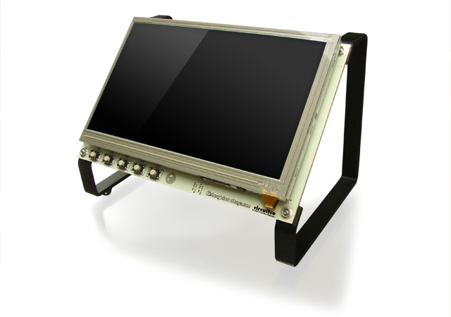
Figure 9-1. Seven-inch LCD from CircuitCo 1
To make this recipe, you will need:
-
Seven-inch LCD ...
Get BeagleBone Cookbook now with the O’Reilly learning platform.
O’Reilly members experience books, live events, courses curated by job role, and more from O’Reilly and nearly 200 top publishers.

