17.7 DESIGN 1: USING d1 = [1 0]t
A point in the dependence graph p = [i j]t will be mapped by the projection matrix P1 = [0 1] onto the point
(17.34)
![]()
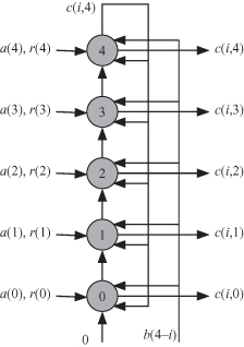
The ![]() corresponding to the projection matrix P1 is shown in Fig. 17.3. DAG consists of m nodes or tasks, and each task is active for m time steps. The algorithm requires m = 5 clock cycles to complete. Notice that signal b(m − 1 − i) is broadcast to all nodes as indicated by the line to the left of the processor array. Notice also that the output of c(i, j) associated with task Tj is sent to the next task Tj+1 at the end of time step i. At the end of time step i, all outputs c(i, 0), c(i, 1), … , c(i, m − 1) are obtained from tasks T0, T1, … Tm − 1, respectively.
corresponding to the projection matrix P1 is shown in Fig. 17.3. DAG consists of m nodes or tasks, and each task is active for m time steps. The algorithm requires m = 5 clock cycles to complete. Notice that signal b(m − 1 − i) is broadcast to all nodes as indicated by the line to the left of the processor array. Notice also that the output of c(i, j) associated with task Tj is sent to the next task Tj+1 at the end of time step i. At the end of time step i, all outputs c(i, 0), c(i, 1), … , c(i, m − 1) are obtained from tasks T0, T1, … Tm − 1, respectively.
Figure 17.3 Task processing workload details at each SPA stage for the left-to-right shift-and-add field multiplication algorithm for m = 5 and d1 = [1 0]t. The signals c(i, 4 − i) and b(4 − i) are shown at time step i, where 0 ≤ i < 5.
Get Algorithms and Parallel Computing now with the O’Reilly learning platform.
O’Reilly members experience books, live events, courses curated by job role, and more from O’Reilly and nearly 200 top publishers.

