Chapter 1. Introduction to the X Window System
The X Window System
The X Window System is a portable, network-based display system. That short definition contains three of the keys to X’s success:
- Portable
The X Window System is primarily used on Unix, Linux, and BSD systems, but it can also be used on Microsoft Windows, Mac OS X, and many other systems—in fact, it can be used on just about any modern operating system. It supports a wide range of hardware, from PDAs and standalone terminals to multimonitor workstations and information displays. Technology may be mixed and matched to suit user preferences, needs, and budget.
- Network-based
Programs can display anywhere on the network, and windows from programs running on machines several time zones apart can be displayed side-by-side on one screen. With X, users have complete freedom to work wherever they want.
- Display system
X is not a graphical user interface (GUI), but it provides a solid foundation for building one. GUI developers can escape from dealing with the intricacies of the display hardware and focus on user interface design, and legacy applications written for decades-old X-based GUIs will continue to work with modern ones.
Although most users of Unix (or Linux, or FreeBSD, or Darwin) often take X for granted, a good understanding of how it works opens up a world of possibilities, from speeding up remote access to building personal video recorders to configuring multiuser computers and information kiosks.
In this book, I assume that you have used X and that you have a basic understanding of Unix. This chapter introduces some of the history and basic concepts of X as well as the hardware technology used in modern displays; this sets the stage for the rest of the book, which uses a hands-on approach.
The History of X
X originated at MIT in 1984. It was a part of Project Athena, a campus-wide, crossplatform system, and it was loosely based on the W Window System from Stanford.
Before long, Unix vendors started to gain an interest in X. They realized that X would make it easier to port graphical applications to new hardware, which in turn would attract independent software vendors (ISVs)—and the more software became available, the more systems would be sold.
After a brief flirtation with restrictive licenses, version 11 of the X Window system was released in 1987 under the MIT license, and a vendor-neutral group called The X Consortium was formed to manage development. This was one of the earliest examples of an open source project. In fact, it predates the term open source by more than a decade. Each vendor used the sample code from the X Consortium as a starting point and implemented a server tuned for their particular display hardware and operating system.
Control of X passed from group to group until 1999, when X.org was established by The Open Group to manage the technology. Unfortunately, official work on X had almost come to a standstill by that point.
However, one particular implementation of X for PCs, named X386, piqued the interest of many developers in 1992. When distribution of a commercial version of X386 began, the open source version was renamed XFree86 (say both names aloud to realize the pun). Eventually, most X innovations were made within the XFree86 project rather than coming from the official guardians of the X standard.
But internal politics and a rigid organizational structure took their toll on the The XFree86 Project, Inc, and after a license dispute in 2003, some key developers decided that they’d had enough. They moved development back to the almost-defunct X.org, formed The X.org Foundation, and shifted work into high gear. Most open source operating system distributions adopted the X.org server in 2004.
In the end, active X development wound up where it had started, the successor to the XFree86 project replaced the sample implementation of X technology, and a revitalized developer community started to once again steadily advance the state of the technology.
The Renaissance: New X Versus Old X
I recently skimmed through the 1994 book X User Tools, by Linda Mui and Valerie Quercia (O’Reilly), and the 1993 UnixWare user documentation. It was a fun and nostalgic stroll down memory lane, because the X Window System I used in the early-to-mid 90s was very different from X today. Many of the changes have been introduced so gradually that it’s only by looking at old screen dumps that I realize how far we’ve come.
I have started to think of X development in terms of two eras: Old X (1984–1996) and New X (2000–present). Old X was characterized by the development of the core protocols, essential extensions, and Xt-based toolkits. New X development was kicked off by the release of the RENDER extension in 2000, which, along with Xft, OpenGL, the COMPOSE extension, and non-Xt toolkits (Qt and KDE), is causing large portions of the core X protocol to fall into disuse. Between these two eras, X development almost came to a standstill.
Here is a summary of some of the key differences in the technology of the two eras:
|
Element |
Old X |
New X |
|
Fonts |
Bitmapped fonts and scalable fonts without anti-aliasing, rendered by the core font capabilities in the server. |
Scalable fonts with full antialiasing, managed on the client side by fontconfig, and displayed by the Xft library using the RENDER extension. |
|
Desktop environments |
No standard desktop environments (though HP Vue morphed into CDE and made a late appearance). Consequently, window managers played a much larger role than they do today. Panel bars were rare— icons for minimized windows sat directly on the desktop (or, sometimes, in a separate icon box window). Clients were usually started through root-window menus or by typing commands in an xterm. |
Two widely used desktop environments (KDE and Gnome) and a lightweight desktop (Xfce) with well-integrated root desktop, menu, and panel-bar operation. |
|
Toolkits and configuration |
Lots of Xt-based toolkits, including Motif, OpenLook, and the Athena Widgets. All of the toolkits could be configured through resources. |
Xt has almost completely fallen into disuse; Qt and GTK+ have captured developer mindshare. Each provides their own configuration systems. freedesktop.org has coordinated shared standards for desktop menu entries and icons. |
|
Display hardware |
Entry-level desktop displays starting at 0.45 megapixels (800x600) and ranging up to 1.25 megapixels on the high end, with a typical resolution of 75 dots per inch (dpi). Common color capabilities ranged from monochrome to 256-color palettes, with very few high-end systems providing full-color capabilities. Palette management issues were a major headache. 3D hardware was rare and very expensive. LCD displays were rare except on laptops, which seldom exceed 0.75 mega-pixels (1024x768). |
24-bit palette-free color with 3D capabilities, and hardware acceleration is standard issue. 0.75 megapixel resolution (1024x768) is considered entry level; high-end systems have multimegapixel displays at resolutions up to 200 dpi. 1.25 megapixel and higher laptop displays are common. Hand-held systems sport resolutions of 320x400 and up. |
|
Client appearance |
Low-resolution, high-contrast (to work with the display hardware) with minimal customizability. |
Shading, gradients, and fine visual details take good advantage of hardware capabilities. Themes provide extensive opportunities for easy customization. |
X by Any Other Name
The X Window System goes by many different names, and sometimes this is a source of confusion. According to the manpage, X should be referenced using one of these names:
X
X Window System
X Version 11
X Window System, Version 11
X11
Notice that “X Windows” is not on that list; this omission was originally due to concern about confusion with Microsoft’s Windows product line.
This has been used as a shibboleth for many years; anyone referring to “X Windows” was considered an outsider or a beginner. Fortunately, this pedantry is waning, but you should probably avoid saying “X Windows” if you find yourself in the company of an industry old-timer.
The version number is almost never mentioned in modern usage, since the previous versions were experimental, and Version 11 has been in use for almost two decades (though the release number keeps going up).
The dominance of the X.org implementation has led a number of people to refer to X itself as Xorg or X dot org.
Seven Layers of an X-based GUI
It is Unix tradition to assemble solutions out of many small programs rather than to use a single, monolithic program. This approach gives more flexibility, since these smaller building blocks may be combined in different ways to meet different needs.
GUIs based on the X Window System follow this same philosophy—they’re built in layers that can be mixed and matched as needed.
Figure 1-1 shows a simple model of the seven layers found in most X-based GUIs.
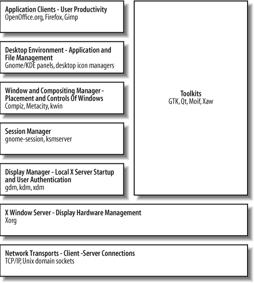
Elements at the top of the diagram are the most visible and important to the user, and the components at the bottom of the diagram are the least visible. From the bottom up, these layers are:
- Network Transport
Enables the other layers to communicate. This layer almost always consists of TCP/IP plus a faster connection scheme for local clients (Section 1.14), but many older or proprietary network transports can be used, including IPX/SPX and DecNET.
- X Window Server
Consists of the software that manages the display (which normally consists of a keyboard, video screen, and mouse) and runs on the computer connected to the display hardware. All of the layers above the X server are considered clients of that server and may be located anywhere on the local network, or even over the Internet.
- Display manager
Enables a user to log in to the system graphically. Most display managers ask the user to type his user ID and password, but it’s possible to use almost any authentication scheme, including biometric scanning.
- Session manager
Tracks application state across login sessions, starting standard clients such as the window manager and desktop environment components, restarting applications that were active at the end of a previous session, and optionally restarting applications if they crash.
- Window and Compositing manager
Manages window placement and provides window decorations. This includes window title bars, borders, and controls for common operations such as resizing, maximizing, minimizing, moving, and closing windows. When the COMPOSITE extension is available, the window manager also acts as the compositing manager. The X developers tried separating them, but in order to work really well, the compositing manager needs access to information about the windows that only a window manager knows. A window manager is considered to be a special class of client, and only one can be active on a display at a time.
- Desktop environment
One or more programs that provide a desktop paradigm for the user. This may include menus to start programs, trays or panels to indicate currently running programs, icons that represent files or programs on the desktop background, docked applets, and other useful tools and utilities.
- Application clients
Programs that enable the user to perform useful work. They are spreadsheets, word processors, web browsers, media players, video editors, and so forth.
- Toolkits
Programming libraries that are used to simplify the task of writing clients that communicate with an X server. Toolkits are not a layer per se, but they do support and simplify the construction of the client layers.
The software used in any layer can be changed without affecting the other layers. For example, you can switch from the XDM display manager to the GDM display manager without making any changes to the other layers.
The bottom two layers (Network Transport and X Server) are mandatory; the other layers are optional. This provides a lot of flexibility in the way that the GUI operates.
For example, the user of an automated teller machine doesn’t need to log in with a user ID, to move or resize windows, or to manage files and start programs, so the display manager, window manager, and desktop environment layers are not needed; the ATM application can directly take control of the entire display space.
Or, if X is started after the user logs in (Section 2.9), the user has already been authenticated, so the display manager is not needed and may be left out.
Where Is the Server?
In most network terminology, the client system is the one that is on your desktop, in your hand, or on your lap, and the server is the computer in the closet down the hall.
But in X terminology, the computer in front of you runs the server, and the client programs may be located on the computer in the closet.
As confusing as this may seem at first, it makes sense if you think in terms of the resource being served. A file server is located where the files are stored; a print server is located at the printer; and a display server is located at the display.
The specific resources managed by an X server include video cards and monitors, pointing devices (such as mice, trackpads, and touchscreens), and keyboards. These are each located at the physical machine running the X server.
Why Windows Look and Act Differently
The programs that access and use display resources are the clients. They may be on the same computer as the server, or they may be located down the hall, or they may be on the other side of the planet.
One of the early tenets of the X Window developers was that X should provide a mechanism for implementing a GUI, but should not impose any policy on how that GUI should operate. This has been both a blessing and a curse throughout the history of X.
Since X does not define policy, the look and feel of applications has been left up to application and toolkit developers, and there is a tremendous variation between programs. The advantage is freedom to experiment and innovate; the disadvantage is confusion for users.
On one of my systems, I have three different calculators available: xcalc, kcalc, and gnome-calculator, as shown in Figure 1-2.
As you can see from this screen dump, each calculator looks different: the fonts, colors, button sizes, menu options, icons, and status bar vary from program to program. They also use different visual effects when buttons are pressed.
Fortunately, the toolkit developers have assumed responsibility for many policy issues, and programs based on the same toolkit generally operate in a consistent way. Programs using different toolkits still behave differently, but the most popular toolkits have converged in their look and feel; notice the similarities between the 3D buttons and the fonts used by kcalc (center) and gnome-calculator (right).
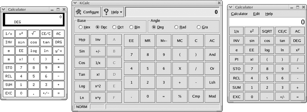
One more thing to note in Figure 1-2: each window’s title bar, border, and window controls are the same—because they are being drawn by the window manager, not the individual application programs.
Toolkits and Desktop Environments
There are three main toolkits currently in use, and desktop environments have been based upon each one:
|
Toolkit |
Original programming language |
License |
Open source |
Desktops built with this toolkit |
|
GTK+ |
C |
GPL |
Yes |
Gnome, Xfce |
|
Qt |
C++ |
GPL |
Yes |
KDE |
|
Motif/OpenMotif |
C |
Open Group Master Software License/Open Group Public License |
No |
CDE |
Most of these desktop environments are distributed with a display manager, window manager, and some application clients, but you can mix and match components from different environments. The use of one desktop environment does not prevent you from using applications built with another toolkit or distributed with another desktop environment, so you can use KDE along with GTK+ apps, or Xfce with Motif applications.
Almost all new development is now based on the GTK+ and Qt toolkits, primarily because they are open source (http://opensource.org) and therefore more accessible to developers.
However, Motif continues to be an important toolkit for legacy applications, especially in some financial and scientific niche markets. Motif and OpenMotif are essentially the same product, distributed under different licenses. While the Open Group Public License does permit OpenMotif to be freely distributed, this is for use only with open source operating systems such as FreeBSD or Linux , so the license does not meet the Open Source Definition (http://opensource.org/docs/osd) or the Debian Free Software Guidelines (DFSG, http://www.debian.org/social_contract#guidelines). Therefore, Motif is not included in most open source operating systems. The Open Group has stated that it intends to switch to a more open license, but it has been slow to do so; meanwhile, the LessTif project (http://www.lesstif.org) has reimplemented most of Motif’s functionality under the GPL.
Motif is the last widely used toolkit based upon the X Intrinsics Toolkit (Xt), an object-oriented library written in C. In addition to Motif, there were widget (user-interface object) sets from the Athena project (Xaw), 3D versions of the Athena widgets (Xaw3d), Sun’s , OpenLook (Olit) , Motif-OpenLook crossover widgets (Moolit) and others. All of these have fallen into disuse, but you may encounter them in older programs from time to time.
The Role of Freedesktop.org
There’s more to a desktop than just a display—there’s also sound, filesystem integration, on-the-fly hardware discovery, and much more. All of these bases must be covered in order to produce a desktop environment that can compete with commercial offerings such as Microsoft Windows or Mac OS X.
Recognizing this, developers have rallied around freedesktop.org, creating an informal consensus-building forum for desktop-oriented technologies. Freedesktop.org (the web site address is the same as the project’s name) hosts much of the work of the revitalized X.org project, coordinates standards between Gnome and KDE, and supports the development of complimentary technologies such as D-BUS and HAL.
freedesktop.org’s lightweight organization and focus on collaboration have made it the centerpiece for most desktop-oriented open source software development.
Display Hardware
Let’s take a look at the hardware typically managed by an X server. It generally has the following components:
Zero or more pointing devices (mice, trackballs, touchscreens).
Zero or more keyboards.
One or more video cards, each connected to one or more monitors.
The entire collection of hardware is called a display and is managed as a single unit, intended to be used by one person. It is possible to have multiple displays connected to one computer, but a separate X server needs to be run for each display.
Pointing Devices
Pointing devices fall into two general categories: relative and absolute:
- Relative pointing devices
These send only movement information to the display. A new pointer position is calculated by taking the previous pointer position and updating it with the indicated movement. Mice, trackpads, and trackballs fall into this category.
- Absolute pointing devices
These send an exact screen position to the display. Touchscreens, graphics tablets, and light pens are all absolute devices.
It is possible to have multiple pointing devices connected to one display. This is common on laptops; some have two built-in pointing devices, and some users add a traditional mouse to compliment a built-in pointing device. The devices act in parallel, and any can be used to move the pointer on the screen (Section 4.8).
A display is rarely configured without a pointing device, but this may be done for an information-only display that does not permit user interaction.
Pointing devices are connected to the computer using a USB, PS/2, serial, or blue-tooth connection. The data rate is very low, so USB pointing devices always run at low speed (1.5 Mbps) even when they are certified to USB 2.0 standards. PS/2 and serial interfaces are electrically identical but have different connectors; you can buy adapters to convert one to the other.
A few years ago, there were dozens of communication protocols used by mice. Fortunately, almost all mice now use an extended version of the PS/2 mouse protocol, regardless of how they are connected, though graphics tablets, touch screens, and the other more exotic pointing devices still use unique protocols.
By far the most popular pointing technology is now the optical mouse. Invented by Agilent (formerly HP), an optical mouse contains a simple high-speed monochrome video camera, a Digital Signal Processor ( DSP), and interface electronics, all on a single chip. The video camera acquires images of the desk or mousepad at the minimum rate of 1,500 frames per second, and the DSP compares each frame with the previous frame to detect movement. When movement is detected, it is communicated with the host computer through the interface electronics, which may be serialor radio-frequency-based (RF). Buttons and a rotary encoder for the scrollwheel round out the unit. Although optical mice outperform mechanical mice in most environments, they require a slightly textured or speckled surface to work well (hence, the sudden popularity of speckled and woodgrain patterns on office furniture instead of the solid colors popular a few years ago). I’ve found that they may be sensitive to bright light at a low angle (such as sunlight at sunrise or sunset), which may cause them to skip or temporarily stop functioning.
Keyboards
Like mice, keyboards are sometimes used in parallel. This is most common on lap-tops, where an add-on numeric keypad may be used along with the built-in key-board, or a larger external keyboard is used in preference to the internal one.
Keyboards typically have PS/2 or USB connectors; USB versions always operate at low speed (1.5 Mbps). The keyboard sends a scancode corresponding to a button location when that button is pressed, and sends another code when that button is released. This permits the system to detect how long buttons are held down and in what combination.
In order to convert these scancodes into characters, the system needs to know which symbol is associated with which key. This is done through a keyboard map. Since most English North American keyboards have a standard layout, one standard key-board map usually suffices; but outside of English North America, additional symbols will appear, either supplementing or replacing the English North American symbols. For example, a U.K. keyboard layout will include symbols for the Euro and pound.
The layout of the basic roman letter symbols will also vary; in North America, the top row starts with QWERTY; in Germany, it often starts QWERTZ; and in France, AZERTY. Nonroman alphabets obviously have their own distinctive layouts as well, but typically provide some way to type roman letters for email addresses, URIs, and code.
Some languages use large numbers of accented characters. Keyboards set up for these languages often use dead keys , which don’t actually type a character, but which cause the following character to be accented. This handling is performed by the system and not by the processor in the actual keyboard, so the operation of dead keys can be reconfigured as needed. A compose key is a special type of dead key that builds a character based on two subsequent keypresses. So, the user might press compose, /, c to produce the cent symbol (¢)or compose, c, comma to produce the letter c with a cedilla (ç).
The most complex keyboard input methods are required for Asian languages, which have very large alphabets of ideographs (idea-pictures). Input methods for Asian languages typically involve entering several keystrokes to phonetically or structurally describe the desired character; if this does not narrow down the selection to a single glyph, then the final selection is performed graphically. Although these input methods require multiple keystrokes per character, each character conveys more meaning, so the average typing speed can be similar to that attained in languages with smaller alphabets.
Most keyboards contain a simple microprocessor and a serial or USB interface, and have three LEDs to indicate keyboard status.
Monitors
All video systems work by scanning dots (or pixels—picture elements) from left to right, top to bottom on the display. For each pixel on a color display, three pieces of information are sent: the individual brightness levels for the red, green, and blue (RGB) components of that dot. The monitor combines the appropriate amount of red, green, and blue light to form the specified color on the screen. Additional signals are used to synchronize the horizontal and vertical scanning so that pixels are drawn in the correct position.
Cathode ray tube (CRT)
CRT monitors draw pixels by shooting electron beams at colored phosphor dots coated onto the inside of the front glass panel, which then glow. It takes a significant amount of energy to create the electron beams, and X-rays are produced as a side effect. In order to shield the user from these X-rays, a significant amount of lead is embedded into the glass of the CRT. Large electromagnets are used to bend the electron beams as the display is scanned.
CRTs are a proven, reliable, and inexpensive technology, and they present a clear image over a wide range of viewing angles. However, their large size, the use of lead in their construction, their high energy usage, and concern over X-ray and electromagnetic radiation has caused many people to consider alternatives.
Liquid crystal display (LCD)
LCDs use light-gates made out of tiny liquid cells adjacent to a polarizing filter. By applying an electric current to the liquid, it can be polarized, allowing more or less light to flow through the light gate. Each pixel is made up of three liquid crystal cells, each with a colored filter—one each for red, green, and blue. Fluorescent lights or white LEDs placed behind the LCD panel provide illumination.
LCDs use less power and space than CRTs, but have a narrower range of acceptable viewing angles, may wash out in bright light, and typically have a less durable front surface than CRTs. Some graphic artists prefer CRTs, claiming that they reproduce a wider range of colors with greater accuracy.
To display images of different resolutions on a CRT, the width of the electron beams is changed, making the pixels larger or smaller. On an LCD, each pixel has a defined location and size, so using a resolution other than the “native” resolution of the display requires some hardware pixels to show a blended color representing a portion of two or more pixels from the image. This results in an undesirable blurring, softening, or blocky presentation of the image, so it is always best to run an LCD at its native resolution.
Other flat-panel technologies
Other flat-panel technologies available include:
- Plasma displays
These use charged gases to produce an image that is bright and that can be very large, but that has a high power consumption and whose brightness diminishes over time, so this type of display’s market share is diminishing as large-format LCD manufacturing becomes feasible.
- Organic Light-Emitting Diode (OLED) displays
These are “printed” onto a flexible substrate. They are currently used on some cell phones and portable music players and hold promise for large, inexpensive display panels once manufacturing issues are refined.
- Electronic paper (or electronic ink) technology displays
These use thousands of tiny cells that can be placed in a particular color state and then stay in that state until changed. There are several different approaches to cell construction, but all electronic paper displays are reflective and use ambient light to illuminate the display. This results in a familiar experience for the user and offers very low power consumption for displays that rarely change. Electronic paper displays are used on some cell phones and e-book readers, and may eventually be used for certain types of monitors, signs, and even billboards.
Video projectors
A video projector can also be considered a type of monitor. Projectors either use LCD technology or thousands of tiny mirrors mounted directly on a Digital Light Processor (DLP) chip. This is coupled with a high-power light, projection lenses, a cooling system, and control electronics.
The control electronics in video projectors are usually more sophisticated than the circuits found in CRT or LCD monitors:
Images can be flipped left to right (for rear-projection applications) or top to bottom (for upside-down ceiling mounts).
Keystone correction permits the sides of the image to be slanted (and the top of the image to be made smaller than the bottom, or vice versa) so that the image will appear rectangular when projected onto the screen at an angle.
Image scaling and multiple video inputs enable a clear picture to be projected despite huge variations in the resolution, quality, and speed of the incoming signals.
Video timing
When dealing with video signals, timing is everything. In order to display a stable picture and accurately locate each dot during the scanning process, the timing of the video signal must be very precise.
The speed of the video signal is dictated by the screen resolution and refresh (scan) rate. Resolution is defined in terms of horizontal and vertical pixels; scan rate is expressed in Hertz (Hz), or cycles per second. A scan rate of 70 Hz or higher is recommended for CRTs in order to reduce eyestrain for the user; the refresh rate is not as important for most LCD displays, because the decay time (the time it takes a pixel to change color) is longer.
The length of cable that may be used to connect a video monitor to a video card is directly limited by the scan rate. A cable stores a small amount of energy between conductors; this quality is called capacitance, and it limits the cable’s ability to handle fast signals. The longer the cable, or the poorer the insulator, the more energy is stored. This restricts the maximum refresh rate that can be used without noticeable image degradation.
Monitor connections
Monitors connect to a video card using one of these standard connection schemes:
- Television
All of the color, luminosity (brightness), and synchronization information is encoded into a single composite analog electrical signal. This type of signal is most useful for connecting to consumer video equipment such as a VCR or television; the standard connector is a coaxial “RCA” plug.
One variation on a television video signal is S-Video, which separates the luminance and chroma (color) information onto separate wires; many video cards that have a “TV Out” feature use this type of connector. In Europe, a rectangular SCART connector is standard and may include a composite signal.
- VGA
An analog connection scheme that uses varying voltages on three separate pins to control the RGB levels. Additional pins are used for synchronization and device probing. The most common physical connector for VGA signals is an HD15—a high density, 15-pin mini D-shaped connector. “VGA” comes from video graphics array , which is the name of the original IBM graphics card that used this connector.
- Digital Visual Interface (DVI)
A modern connector that supports analog signals, digital signals, or both. DVI-D includes digital signals only; DVI-I includes both; and the unofficial DVI-A connector includes analog only.
DVI-I and DVI-A can be connected to VGA equipment through a simple adapter. Where possible, though, the digital signal should be used for greater accuracy and clarity.
DVI-D supports dual-channel connections for high-resolution displays (above 1.25 megapixels) and may use high-bandwidth digital content protection (HDCP) signal encryption.
- High Definition Multimedia Interface (HDMI)
HDMI provides an easy-to-use single connector that incorporates a DVI-D compatible digital video signal and digital audio. It is common on high-definition television equipment and monitors, but so far is not used often on computers. HDCP may be used with HDMI. There are two connectors in use: Type A, which supports single-channel connections, and Type B, which has additional conductors to carry a dual-channel signal.
- DisplayPort
An alternative to HDMI that provides a similar pure-digital audio and video signal with optional HDCP encryption. While HDMI was intended as a consumer specification for entertainment devices, DisplayPort initially targets computer systems. The Video Electronics Standard Association ( VESA) backs the Display-Port standard and has established compliance testing programs for it, which will ensure interoperability of DisplayPort devices. Offering support for color depths beyond 24 bits per pixel (16 million colors) and the potential of an easy future upgrade to fiber optic connection, DisplayPort is a strong specification. But, it is late to market, and it may be difficult to unseat entrenched standards such as HDMI.
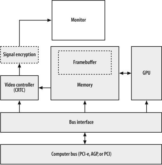
Video Cards
The circuitry that drives the monitor is contained on a video card or integrated into the system motherboard.
There are four main components in a video card, as illustrated in Figure 1-3:
- Memory
An area of memory set aside to keep track of the image on the screen (the framebuffer ) and other video-related data such as pixmaps, save-unders, and images that will be composed into the framebuffer by the GPU.
Historically, successive generations of video cards have swung back and forth between using a reserved area of main system memory for the framebuffer and using a completely separate bank of physical memory. Any memory over and above the memory used for the framebuffer may be used for fonts, off-screen rendering, save-unders (remembering what is underneath windows), and texture maps.
- Graphics processing unit (GPU)
Performs graphics operations such as block moves, line drawing, area fills, shad-ing, and texture mapping independently from the system’s CPU. Most modern GPUs handle 3D operations, although some of the lower-end devices (typically built into motherboards) have very weak 3D performance.
- Bus interface
Connects the host system bus to the memory and GPU. PCI Express (PCI-E) is the preferred connection path on most new systems; an accelerated graphics port ( AGP) or legacy PCI interface may also be used.
- Video controller
Generates the video signal by repeatedly scanning the framebuffer and converting the pixel information into the format required at the video connector. If an analog connection is used, multiple digital-to-analog converters ( DACs) are incorporated to convert the digital brightness values into varying voltages; the DACs speed often limits the maximum refresh rate available at a given resolution. Some graphics systems with DVI, HDMI, or DisplayPort connectors incor-porate encryption chips between the video controller and the video connector.
- Signal encryption
This optional circuit encrypts the signal for content protection using HDCP or a competing protocol.
The screen image can be represented in the framebuffer in one of two ways:
The RGB information for each pixel can be stored in successive memory locations. On modern video cards, 8 bits (1 byte) of informaton is stored for each RGB channel, resulting in a total of 24 bits (3 bytes) of memory used for each pixel. This permits 224 = 16 million colors to be used simultaneously on the display. It is also fairly common to use 8, 15, or 16 bits per pixel, and less common (on specialized cinema-oriented hardware) to use 12 or 16 bits per RGB channel for a total of 36 to 48 bits per pixel.
A color code for each pixel can be stored. This results in a “paint-by-number” scheme, where the video controller looks up each color code in a palette or lookup table to determine the RGB value. For example, the color code 3, when stored in the memory location for a given pixel, would instruct the video controller to look up entry number 3 in the palette and use whatever color is stored there.
Palette-based color is rarely used on modern PCs, but is common on smaller devices such as PDAs and cell phones. It may seem absurd to talk about PDAs and phones in a book about X, but they now have sufficient computing power to viably run an X server!
The size of a framebuffer in bytes is:
WidthInPixels * HeightInPixels * BytesPerPixel
Therefore, a 1280x1024 display with 3 bytes (24 bits) per pixel of color information would take:
1280 x 1024 x 3 = 3932160 bytes = 3.75 MB
Note that since most modern CPUs deal with memory in 32-bit words, many 24-bit video modes actually devote 32 bits to each pixel to simplify manipulation of the data. This wastes 8 bits per pixel, but the resulting increase in speed makes it worth-while. If the video card in the preceding example used 32 bits per pixel, the memory required would be 5 MB.
Displays, Screens, and Xinerama
In X terminology, a display comprises the user interface for one person. That usually means one keyboard, pointer, video card, and monitor, but for some applications, more video “real estate” is required. Thus, a display can have multiple video cards and monitors, perhaps with different capabilities and resolutions—but this is where the terminology gets tricky.
All of a display’s video cards and monitors can be combined to act like one giant video monitor. This approach is called Xinerama (Section 4.9) as a tribute to the old Cinerama multiprojector wide-screen movie format. Xinerama permits windows to span monitors and works especially well on multipanel LCD displays, video walls, or video projectors.
Alternately, a display’s video cards and monitors may be configured as separate screens . Each screen is individually addressable, so windows can be directed to display on a specific screen. It is not possible to move windows between screens nor to have windows span screens, but the mouse pointer can be moved between screens. The use of screens predates Xinerama, but it is still useful for some dual-monitor applications, such as presentations where one monitor is used for control and setup and the second monitor displays live output to the audience. By using a two-screen configuration instead of Xinerama, windows from the control screen will be prevented from straying onto the publicly-visible display.
Some window managers, such as the LessTif version of the Motif Window Manager MWM, are not capable of managing multiple screens and will only register them-selves as the window manager for one screen. On the other hand, some toolkits are not aware of Xinerama, so dialogs that are intended to be positioned in the center of a display always display in the middle of the Xinerama display—and therefore always span across monitors in a dual-monitor Xinerama configuration (which is very, very annoying).
Each display (regardless of the number of screens involved) is managed by exactly one X server process.
Display Specifications
Since X clients can connect to a display anywhere on the network, it is necessary to have some way of specifying the display to be used. This is done using a display specification (or displayspec).
A displayspec takes this form:
host:display[.screen]The following list describes each element in a displayspec:
-
host The name or network address of the system running the X server. This may be:
A DNS hostname or IP address
Blank, or the word
unix, indicating a local host connection (Section 1.14)A DecNET, IPX/SPX, or other machine designation (extremely rare)
-
display -
screen An optional screen number within the display; screens are numbered starting at zero
Here are some examples:
The displayspec can be passed to clients as an option value:
$ xclock -display displayspecHowever, it is more common and convenient to use the DISPLAY environment variable. If you are using a shell that follows the Bourne syntax(sh, bash, ksh, zsh, or ash), you can set and export the DISPLAY variable like this:
$ export DISPLAY=displayspecIf you are a csh aficionado, use:
% setenv DISPLAY displayspecOnce the DISPLAY variable has been set, any new clients started will connect to the specified display by default. (Command-line options take precedence over the DISPLAY variable.)
TCP/IP Ports
Each X display uses a unique TCP/IP port so that multiple servers on the same system do not conflict. All of the screens managed by one display are accessed through the same port; screen selection is accomplished through the X protocol.
The standard port for an X server is 6000+display, so display :0 uses port 6000, and display :15 uses port 6015. Since these port numbers are over 1024, the kernel permits anyone to open them—so you don’t need to be root to run an X server. Large display numbers may conflict with other services (such as IRC at port 6667), so it is best to keep display numbers under 100.
Local Connection Mechanisms
TCP/IP is a great network transport, but it’s overkill for connecting programs running on the same computer. Most X servers provide a faster alternative for local connections.
Unfortunately, there are at least five different local connection schemes in use, including Unix domain sockets, named pipes, and various types of Streams pipes. Open source operating systems use Unix domain sockets without exception.
A displayspec with a blank host field will automatically select the default local connection scheme; if the default isn’t a Unix domain socket, then some systems permit a host value of unix to force a domain socket to be used.
Unix domain sockets for the X server are created in /tmp/.X11-unix and are named according to the display number (therefore, /tmp/.X11-unix/X0 is the Unix domain socket for local display :0).
After a local connection has been established, the client and server can negotiate the use of shared memory for faster communication of large blocks of data; this requires the MIT SHM extension.
Binaries compiled for one platform but executed on another may not interpret a blank hostname field in the displayspec correctly. For example, binaries compiled for SCO Unix may default to a Streams mechanism. When running under Linux using the iBCS compatibility layer, this will cause a problem, because Linux doesn’t support Streams. In this case, a hostname value of unix should force the use of Unix domain sockets; as a last resort, the TCP/IP local loopback mechanism can be used by specifying a hostname of localhost (however, this incurs the extra overhead of the TCP/IP stack—twice).
Server Extensions
The X11 protocol was designed to be enhanced by adding extensions to the X server. Clients can query the server to find out what extensions are available. This has enabled many features to be added through the years without significant changes to the core protocol (which explains why we’re still using version 11!).
Extensions may be compiled in to the X server, or they may be loaded as modules. Because their presence is optional, the X server can be slimmed down for use on small machines by building it with a smaller set of extensions.
Here are some of the key extensions in widespread use (upper-and lowercase names are those reported by the extensions themselves using xdpyinfo (Section 6.2):
- MIT-BIG-REQUESTS
Permits client requests over 256 Kb, necessary to draw complex images.
- MIT-SHM
- Composite
Enables off-screen rendering of windows, which are then combined (composited) into the final screen image by hardware under control of a compositing manager. This is usually integrated into the window manager. During composition, images can be distorted, blended, and resized, so the extension provides an easy way to add drop shadows, window transparency, icons, and thumbnails that are “live,” smooth window resizing, and many other 2D and 3D visual effects.
- DAMAGE
Informs a client when one part of the display has been updated. Reduces unnecessary drawing and improves the efficiency of applications such as VNC (Section 14.1).
- DPMS
Displays Power Management Signalling. Enables the X server to reduce monitor power consumption when not in use (Section 3.11).
- GLX
OpenGL extension for X11. Enables clients to send OpenGL 3D commands to the X server, which then passes them on to 3D video hardware (or performs the 3D operations in software if necessary—which is very slow!).
- LBX
Low-Bandwidth X. Used with
lbxproxyto reduce bandwidth requirements and latency for remote clients (Section 13.11).- MIT-SCREEN-SAVER
The eye-candy extension! MIT-SCREEN-SAVER informs screensavers when start and stop (Section 14.3).
- RANDR
Stands for rotate and resize. Notifies clients when the display is resized to a new resolution or rotated (useful on tablet PCs and LCDs on pivot mounts) and enables the hot-plugging of monitors (Section 5.2).
- RECORD
Permits X events to be recorded for later analysis or playback. Used to automate application testing and provide macro facilities.
- RENDER
Provides a digital image composition model. Render simplifies tasks such as alpha blending (combining partially transparent images) and high-quality antialiased text display (Section 11.1).
- SECURITY
Divides clients into two categories—trusted and untrusted—and prevents untrusted clients from accessing data held for trusted clients. Properly used, this can reduce the risk of compromise due to actions such as keystroke logging (to steal passwords) or remote screen dumping (to view sensitive information displayed on the screen). ssh now supports this extension (Section 13.10).
- SHAPE
Enables nonrectangular windows. The
xeyesandoclockclients provide a good demonstration of this capability.- SYNC
Makes it possible to synchronize the X display with external events—for example, keeping a movie soundtrack synchronized with the picture.
- XInputExtension
Provides support for specialized input devices such as graphics tablets, dial boxes/control surfaces, and 3D trackballs.
- XKEYBOARD
Enables complex keyboard mapping and configuration (Section 12.1).
- XTEST
Extends the X protocol to simplify performance benchmarking.
- XINERAMA
Single-screen, multimonitor support (Sections 1.11 and 4.2).
- XVideo
Enables video streams, such as those from a video camera or TV tuner card, to be converted, transformed, and then overlaid on the X display. This is done with hardware support and can dramatically improve video performance (Section 4.1).
- XVideo-MotionCompensation
Utilizes hardware support for video decompression—useful for DVD viewing and other MPEG video playback.
Where to Draw the Line: Kernel Versus User-Space Drivers
The operating system kernel is usually responsible for managing all of the system hardware, and normal user-space programs access hardware only through the OS. This clear-cut distinction between the kernel and user-space programs has been very difficult to maintain when implementing X servers.
The problem is that video cards vary enormously in terms of their GPU capabilities and general architecture. It’s hard to create a simple, well-defined interface between a video driver in the kernel and an X server in user-space that will work well for all video cards, though several attempts have been made. And of course the X server is too large and complex to safely place it directly into the kernel.
As it stands now, most kernel/X server combinations—including Linux with the X.org server—pretty much give the X server free reign when it comes to video card access, though some of the card drivers (such as the NVIDIA closed-source driver) use a small kernel module to assist them.
This will likely change in the future. The X server may eventually operate as one (of perhaps many) OpenGL clients, removing direct hardware access from the X server entirely. The Xgl server provides a preliminary implementation of this approach.
Get X Power Tools now with the O’Reilly learning platform.
O’Reilly members experience books, live events, courses curated by job role, and more from O’Reilly and nearly 200 top publishers.

