When you place your computer on a network, it interacts with many other systems. The way you do network administration tasks has effects, good and bad, not only on your system but also on other systems on the network. A sound understanding of basic network administration benefits everyone.
Networking computers dramatically enhances their ability to communicate—and most computers are used more for communication than computation. Many computers are busy crunching the numbers for business and science, but the number of such systems pales in comparison to the millions of systems busy moving email to a remote colleague or retrieving information from a remote repository. When you think of the hundreds of millions of desktop systems that are used primarily for preparing documents to communicate ideas from one person to another, it is easy to see why most computers can be viewed as communications devices.
The positive impact of computer communications increases with the number and type of computers participating in the network. One of the great benefits of TCP/IP is that it provides interoperable communications between all types of hardware and all kinds of operating systems.
The name “TCP/IP” refers to an entire suite of data communications protocols. The suite gets its name from two of its protocols: the Transmission Control Protocol (TCP) and the Internet Protocol (IP). The TCP/IP protocol suite is sometimes just called IP. Both names are acceptable. TCP/IP is the traditional name for this protocol suite and it is the name used in this book.
Protocols are the rules of data communications. The software that network administrators deal with implements those protocols. This book is a practical, step-by-step guide to configuring and managing TCP/IP networking software on Windows server systems. TCP/IP is the leading communications software for local area networks and enterprise intranets, and it is the foundation of the worldwide Internet. TCP/IP is the most important networking software available to a network administrator.
The first part of this book discusses the basics of TCP/IP and how it moves data across a network. The second part explains how to configure and run TCP/IP on a Windows server. Let’s start with a little history.
In 1969, the Advanced Research Projects Agency (ARPA) funded a research and development project to create an experimental packet-switching network. This network, called the ARPANET , was built to study techniques for providing robust, reliable, vendor-independent data communications. Many techniques of modern data communications were developed in the ARPANET.
The experimental network ARPANET was so successful, many of the organizations attached to it began to use it for daily data communications. In 1975, the ARPANET was converted from an experimental network to an operational network, and the responsibility for administering it was given to the Defense Communications Agency (DCA) , which has since changed its name to Defense Informations Systems Agency (DISA) . However, development of the ARPANET did not stop just because it was being used as an operational network; the basic TCP/IP protocols were developed after the network ARPANET was operational.
The TCP/IP protocols were adopted as Military Standards (MIL STD) in 1983, and all hosts connected to the network were required to convert to the new protocols. To ease this conversion, DARPA[*] funded Bolt, Beranek, and Newman (BBN) to implement TCP/IP in Berkeley (BSD) Unix. This provided a reference implementation that could be used by anyone who wanted to implement TCP/IP.
About the time that TCP/IP was adopted as a standard, the term Internet came into common usage. In 1983, the old ARPANET was divided into MILNET, the unclassified part of the Defense Data Network (DDN), and a new, smaller ARPANET. “Internet” was used to refer to the entire network: MILNET plus ARPANET.
In 1985, the National Science Foundation (NSF) created NSFNet and connected it to the then-existing Internet. The original NSFNet linked together the five NSF supercomputer centers. It was smaller than the ARPANET and no faster—56 Kbps. Nonetheless, the creation of the NSFNet was significant because NSF brought with it a new vision of the use of the Internet. NSF wanted to extend the network to every scientist and engineer in the United States. To accomplish this, in 1987 NSF created a new, faster backbone and a three-tiered network topology that included the backbone, regional networks, and local networks. In 1990, the ARPANET formally passed out of existence, while the NSFNet ceased its role as a primary Internet backbone network in 1995.
Today, the Internet encompasses hundreds of thousands of networks worldwide. It is no longer dependent on a core (or backbone) network or on governmental support. Today’s Internet is built by commercial providers. National network providers, called tier-one providers, and regional network providers create the infrastructure. Internet Service Providers (ISPs) provide local access and user services. This network of networks is linked together in the United States at several major interconnection points called Network Access Points (NAPs).
The Internet has grown far beyond its original scope. The networks and agencies that built the Internet no longer play an essential role. The Internet has evolved from a simple backbone network, through a three-tiered hierarchical structure, to a huge network of interconnected, distributed hubs, growing exponentially during the 1980’s and 1990’s. Through all of this incredible change, one thing has remained constant: the Internet is built on the TCP/IP protocol suite.
Because TCP/IP is required for Internet connection, the growth of the Internet spurred interest in TCP/IP. As more organizations became familiar with TCP/IP, they saw its power could be applied in other network applications. The Internet protocols are often used for local area networking, even when the local network is not connected to the Internet. TCP/IP is also widely used to build enterprise networks. TCP/IP is the foundation of all of these varied networks.
The popularity of the TCP/IP protocols did not grow rapidly just because the protocols were there, or because connecting to the Internet mandated their use. They met an important need (worldwide data communications) at the right time, and they had several important features that allowed them to meet this need:
Open protocol standards, freely available and developed independently from any specific computer hardware or operating system. Because it is so widely supported, TCP/IP is ideal for uniting different hardware and software, even if you don’t communicate over the Internet.
Independence from specific physical network hardware. This allows TCP/IP to integrate many different kinds of networks. TCP/IP can be run over an Ethernet, a DSL connection, a wireless connection, an optical network, and virtually any other kind of physical transmission medium.
A common addressing scheme that allows any TCP/IP device to uniquely address any other device in the entire network, even if the network is as large as the worldwide Internet.
Standardized high-level protocols for consistent, widely available user services.
Protocols are formal rules of behavior. In international relations, protocols minimize the problems caused by cultural differences when various nations work together. By agreeing to a common set of rules that are widely known and independent of any nation’s customs, diplomatic protocols minimize misunderstandings; everyone knows how to act and how to interpret the actions of others. Similarly, a set of rules is necessary to govern computer communications.
In data communications, these sets of rules are also called protocols. In homogeneous networks, a single computer vendor specifies a set of communications rules designed to use the strengths of the vendor’s operating system and hardware architecture. But homogeneous networks are like the culture of a single country—only the natives are truly at home. TCP/IP creates a heterogeneous network with open protocols independent of operating systems and architectural differences. TCP/IP protocols are available to everyone and developed and changed by consensus—not by the fiat of one manufacturer. Everyone is free to develop products that meet these open protocol specifications.
The open nature of TCP/IP protocols requires an open standards development process and publicly available standards documents. The Internet Engineering Task Force (IETF) develops Internet standards in open, public meetings. The protocols developed in this process are published as Requests for Comments (RFCs). RFCs are available online at http://www.rfc-editor.org. To find out how Internet standards are created, read The Internet Standards Process, RFC 2026.
As the title “Request for Comments” implies, the style and content of these documents are much less rigid than most standards documents. RFCs contain a wide range of interesting and useful information, and are not limited to the formal specification of data communications protocols. There are three basic types of RFCs: standards (STD), best current practices (BCP), and informational (FYI).
RFCs that define official protocol standards are STDs and are given an STD number in addition to an RFC number. Creating an official Internet standard is a rigorous process. Standards track RFCs pass through three maturity levels before becoming standards:
- Proposed standard
This specification is important enough and has received enough Internet community support to be considered for a standard. The specification is stable and well understood, but it is not yet a standard and may be withdrawn from consideration to be a standard.
- Draft standard
This is a protocol specification for which at least two independent, interoperable implementations exist. A draft standard is a final specification undergoing widespread testing. It will only change if the testing forces a change.
- Internet standard
A specification is declared a standard only after extensive testing and only if the protocol defined in the specification is considered to be of significant benefit to the Internet community.
There are two categories of standards. A Technical Specification (TS) defines a protocol. An Applicability Statement (AS) defines when the protocol is to be used. There are three requirement levels that define the applicability of a standard:
- Required
This standard protocol is a required part of every TCP/IP implementation. It must be included for the TCP/IP stack to be compliant.
- Recommended
This standard protocol should be included in every TCP/IP implementation, although it is not required for minimal compliance.
- Elective
This standard is optional. It is up to the software vendor to implement or not.
Two other requirements levels (limited use and not recommended) apply to RFCs not part of the standards track. A “limited use” protocol is applied only in special circumstances, such as during an experiment. A protocol is “not recommended” when it has limited functionality or is outdated. There are three types of non-standards track RFCs:
- Experimental
An experimental protocol is limited to use in research and development.
- Historic
An historic protocol is outdated and no longer recommended for use.
- Informational
An informational RFC provides information of general interest to the Internet community; it does not define an Internet standard protocol.
A subset of the informational RFCs is called the FYI (For Your Information) notes. An FYI document is given an FYI number in addition to an RFC number. FYI documents provide introductory and background material about the Internet and TCP/IP networks. While RFC 2026, The Internet Standards Process , defines most of the document types described above and explains how those documents are used in the standards process, FYI documents are not mentioned in the RFC because they are not included in the Internet standards process. Nevertheless, there are several interesting FYI documents available. To find out more about FYI documents, read RFC 1150, FYI on FYI: An Introduction to the FYI Notes.
Another group of RFCs that go beyond documenting protocols is the Best Current Practices (BCP) RFCs. BCPs formally document techniques and procedures. Some of these document the way that the IETF conducts itself. RFC 2026 is an example of this type of BCP. Others provide guidelines for the operation of a network or service; RFC 1918, Address Allocation for Private Internets, is an example of this type of BCP. BCPs that provide operational guidelines are often of great interest to network administrators.
There are now almost 4,000 RFCs. As a network system administrator, you may read several. With so many to choose from, it is as important to know which ones to read, as it is to know how to understand them. Use the RFC categories and the requirements levels to help you determine which RFCs are applicable to your situation. (A good starting point is to focus on RFCs with STD numbers.) Stick with the most current version of an RFC. (The RFC index found at http://www.rfc-editor.org/rfc-index.html will tell you if an RFC has been made obsolete by a newer RFC.) To understand what you read, you need to understand the language of data communications. RFCs contain protocol implementation specifications defined in terminology that is unique to data communications.
To discuss computer networking, terms with special meanings to network professionals need to be used. Even other computer professionals may not be familiar with all the terms in the networking alphabet soup. As is always the case, English and computer-speak are not equivalent (or even necessarily compatible) languages. Although descriptions and examples should make the meaning of the networking jargon more apparent, sometimes terms are ambiguous, so a common frame of reference is necessary.
An architectural model developed by the International Standards Organization (ISO) is frequently used to describe the structure and function of data communications protocols. This architectural model, which is called the Open Systems Interconnect (OSI) Reference Model, provides a common reference for discussing communications. The terms defined by this model are well understood and widely used—so widely used, in fact, that it is difficult to discuss data communications without using OSI’s terminology.
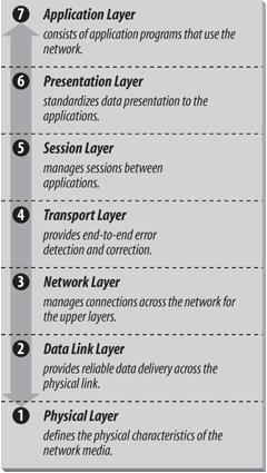
The OSI Reference Model contains seven layers that define the functions of data communications protocols. Each layer of the OSI model represents a function performed when data is transferred between cooperating applications across an intervening network. Figure 1-1 identifies each layer by name and provides a short functional description for it. Looking at this figure, the protocols are like a pile of building blocks stacked one upon another. Because of this appearance, the structure is often called a stack or protocol stack .
A layer does not define a single protocol—it defines a data communications function that may be performed by any number of protocols. Therefore, each layer may contain multiple protocols, each providing a service suitable to the function of that layer. For example, a file transfer protocol (ftp) and an electronic mail protocol both provide user services, and both are part of the Application Layer.
Every protocol communicates with its peer. A peer is an implementation of the same protocol in the equivalent layer on a remote system; i.e., the local file transfer protocol is the peer of a remote file transfer protocol. Peer-level communications must be standardized for successful communication. In the abstract, each protocol is concerned only with communicating to its peers ; it does not care about the layer above or below its peers.
However, there must also be agreement on how to pass data between the layers on a single computer, because every layer is involved in sending data from a local application to an equivalent remote application. The upper layers rely on the lower layers to transfer the data over the underlying network. Data is passed down the stack from one layer to the next, until it is transmitted over the network by the Physical Layer protocols. At the remote end, the data is passed up the stack to the receiving application. The individual layers do not need to know how the layers above and below them function; they only need to know how to pass data to them.
Isolating network communications functions in different layers minimizes the impact of technological change on the entire protocol suite. New applications can be added without changing the physical network, and new network hardware can be installed without rewriting the application software.
Although the OSI model is useful, the TCP/IP protocols don’t match its structure exactly. Therefore, in our discussions of TCP/IP, we use the layers of the OSI model in the following way:
- Application Layer
The Application Layer is the level of the protocol hierarchy where user-accessed network processes reside. In this text, a TCP/IP application is any network process that occurs above the Transport Layer . This includes all of the processes that users directly interact with as well as other processes at this level that users are not necessarily aware of. In most cases, the user’s interaction with an application layer protocol is through a tool that hides most of the protocol from view. An example would be a user’s interactions with the Post Office Protocol (POP) through Outlook. But in some cases, the Windows ftp command is a good example; the user literally enters the protocol commands.
- Presentation Layer
In order for cooperating applications to exchange data, they must agree on how data is represented. In OSI, this layer provides standard data presentation routines. This function is frequently handled within the applications in TCP/IP, though TCP/IP protocols such as External Data Representation (XDR) and Multipurpose Internet Mail Extensions (MIME) also perform this function.
- Session Layer
As with the Presentation Layer, the Session Layer is not identifiable as a separate layer in the TCP/IP protocol hierarchy. The OSI Session Layer manages the sessions (connections) between cooperating applications. In TCP/IP application protocols, the term “session” is used to refer to the connection between cooperating applications, but the functions defined for the OSI Session Layer largely occurs in the TCP/IP Transport Layer. In the Transport Layer the term “session” is not used; instead the terms “socket” and “port” are used to describe the path over which cooperating applications communicate. (Much more on sockets and ports later in this chapter.)
- Transport Layer
Much of our discussion of TCP/IP is directed to the protocols that occur in the Transport Layer. The Transport Layer in the OSI reference model guarantees that the receiver gets the data exactly as it was sent. In TCP/IP, this function is performed by the Transmission Control Protocol (TCP). However, TCP/IP offers a second Transport Layer service, User Datagram Protocol (UDP), that does not perform the end-to-end reliability checks.
- Network Layer
The Network Layer manages connections across the network and isolates the upper layer protocols from the details of the underlying network. The Internet Protocol (IP), which isolates the upper layers from the underlying network and handles the addressing and delivery of data, is usually described as TCP/IP’s Network Layer.
- Data Link Layer
The reliable delivery of data across the underlying physical network is handled by the Data Link Layer. Data Link Layer protocols are rarely defined specifically for the TCP/IP protocol suite. Most RFCs that relate to the Data Link Layer discuss how IP can make use of existing data link protocols.
- Physical Layer
The Physical Layer defines the characteristics of the hardware needed to carry the data transmission signal. Features such as voltage levels, and the number and location of interface pins, are defined in this layer. Examples of standards at the Physical Layer are interface connectors such as RS232C and V.35, and standards for local area network wiring such as IEEE 802.3. TCP/IP does not define physical standards; it makes use of existing standards.
The terminology of the OSI reference model helps describe TCP/IP, but to fully understand it, an architectural model must be used that more closely matches the structure of TCP/IP. The next section introduces the protocol model to describe TCP/IP.
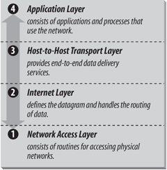
While description of TCP/IP with a layered model is not universally agreed upon, it is generally viewed as being composed of fewer layers than the seven used in the OSI model. Most descriptions of TCP/IP define three to five functional levels in the protocol architecture . The four-level model illustrated in Figure 1-2 is based on the three layers (Application, Host-to-Host, and Network Access) shown in the DOD Protocol Model in the DDN Protocol Handbook—Volume 1, with the addition of a separate Internet layer. This model provides a reasonable pictorial representation of the layers in the TCP/IP protocol hierarchy.
As in the OSI model, data is passed down the stack when it is being sent to the network and up the stack when it is being received from the network. The four-layered structure of TCP/IP is seen in the way data is handled as it passes down the protocol stack from the Application Layer to the underlying physical network. Each layer in the stack adds control information to ensure proper delivery. This control information is called a header because it is placed in front of the data to be transmitted. Each layer treats all of the information it receives from the layer above as data and places its own header in front of that information. The addition of delivery information at every layer is called encapsulation . (See Figure 1-3 for an illustration of this.) When data is received, the opposite happens. Each layer strips off its header before passing the data on to the layer above. As information flows back up the stack, information received from a lower layer is interpreted as both a header and data.
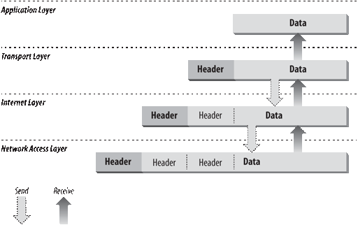
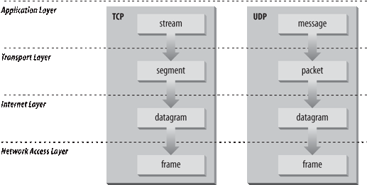
Figure 1-4 shows the terms used by different layers of TCP/IP to refer to the data being transmitted. Applications using TCP refer to data as a stream, while applications using the User Datagram Protocol (UDP ) refer to data as a message. TCP calls data a segment, and UDP calls its data a packet. The Internet layer views all data as blocks called datagrams. TCP/IP uses many different types of underlying networks (e.g., frame relay or token-ring), which may have a different terminology for the data it transmits. Most networks refer to transmitted data as packets or frames . Figure 1-4 shows a network that transmits pieces of data it calls frames.
Following is a closer look at the function of each layer, working up from the Network Access Layer to the Application Layer.
The Network Access Layer is the lowest layer of the TCP/IP protocol hierarchy. The protocols in this layer provide the means for the system to deliver data to the other devices on a directly attached network. This layer defines how to use the network to transmit an IP datagram. Unlike higher-level protocols, Network Access Layer protocols must know the details of the underlying network (its packet structure, addressing, etc.) to format the data being transmitted to comply with the network constraints. The TCP/IP Network Access Layer can encompass the functions of all three lower layers of the OSI reference Model (Network, Data Link, and Physical).
The design of TCP/IP hides the function of the lower layers, and the better known protocols (IP, TCP, UDP, etc.) are all higher-level protocols. As new hardware technologies appear, new Network Access protocols are developed so that TCP/IP networks can use the new hardware.
Functions performed at this level include encapsulation of IP datagrams into the frames transmitted by the network and mapping of IP addresses to the physical addresses used by the network. One of TCP/IP’s strengths is its universal addressing scheme. The IP address must be converted into an address that is appropriate for the physical network over which the datagram is transmitted.
Some examples of RFCs that define network access layer protocols follow:
RFC 894, A Standard for the Transmission of IP Datagrams over Ethernet Networks, specifies how IP datagrams are encapsulated for transmission over Ethernet networks.
RFC 826, Ethernet Address Resolution Protocol (ARP), maps IP addresses to Ethernet addresses. (ARP is covered in Chapter 2.)
RFC 1661, The Point-to-Point Protocol (PPP), specifies how IP datagrams are transmitted over point-to-point connections.
The layer above the Network Access Layer in the protocol hierarchy is the Internet Layer, and the Internet Protocol (IP) is the most important protocol in that layer. The release of IP used in the current Internet is IP Version 4 (IPv4), which is defined in RFC 791. It is called Version 4 because it is identified by the value 4 in the version field of the IP datagram header, which is shown in Figure 1-5. However, IPv4 is the first version of IP deployed in the Internet and it is still in use today.[*] There are later versions of IP. IP Version 5 (IPv5) is an experimental Stream Transport (ST) protocol used for real-time data delivery. IPv5 never came into operational use. IPv6 is an IP standard that provides greatly expanded addressing capacity. Because IPv6 uses a completely different address structure, it is not interoperable with IPv4. While IPv6 is a standard version of IP that is delivered with Windows Server 2003, it is not yet widely used in operational, commercial networks. Our focus is on practical, operational networks, so, while IPv6 is discussed in Chapter 2, we do not cover IPv6 in great detail. In this chapter, and throughout the main body of the text, we refer to IPv4 whenever we say IP. IPv4 is the protocol you will configure on your system when you want to exchange data with remote systems, and it is the focus of this text.
The Internet Protocol is the heart of TCP/IP. IP provides the basic packet delivery service on which TCP/IP networks are built. All protocols, in the layers above and below IP, use the Internet Protocol to deliver data. All TCP/IP data flows through IP, incoming and outgoing, regardless of its final destination.
The Internet Protocol is the building block of the Internet. Its functions include the following:
Defining the datagram, which is the basic unit of transmission in the Internet
Defining the Internet addressing scheme
Moving data between the Network Access Layer and the Transport Layer
Before describing these functions in more detail, let’s look at some of IP’s characteristics. First, IP is a connectionless protocol. This means that IP does not exchange control information (called a “handshake”) to establish an end-to-end connection before transmitting data. In contrast, a connection-oriented protocol exchanges control information with the remote system to verify that it is ready to receive data before any data is sent. When the handshaking is successful, the systems are said to have established a connection. Internet Protocol relies on protocols in other layers to establish the connection if they require connection-oriented service.
IP also relies on protocols in the other layers to provide error detection and error recovery. The Internet Protocol is sometimes called an unreliable protocol because it contains no error detection and recovery code. This is not to say that the protocol cannot be relied on—quite the contrary. IP can be relied upon to accurately deliver data to the connected network, but it doesn’t check whether that data was correctly received. Protocols in other layers of the TCP/IP architecture provide this checking when it is required.
The TCP/IP protocols were built to transmit data over the ARPANET, which was a packet switching network. A packet is a block of data that carries the information necessary to deliver it—in a manner similar to a postal letter, which has an address written on its envelope. A packet-switching network uses the addressing information in the packets to switch packets from one physical network to another, moving them toward their final destination. Each packet travels the network independently of any other packet.
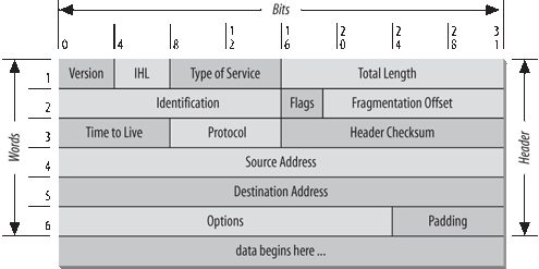
The datagram is the packet format defined by Internet Protocol. Figure 1-5 is a pictorial representation of an IP datagram. The first five or six 32-bit words of the datagram are control information called the header. By default, the header is five words long; the sixth word is optional. Because the header’s length is variable, it includes a field called Internet Header Length (IHL) that indicates the header’s length in words. The header contains all the information necessary to deliver the packet.
The Internet Protocol delivers the datagram by checking the Destination Address in word 5 of the header. The Destination Address is a standard 32-bit IP address that identifies the destination network and the specific host on that network. (The format of IP addresses is explained in Chapter 2.) If the Destination Address is the address of a host on the local network, the packet is delivered directly to the destination. If the Destination Address is not on the local network, the packet is passed to a gateway for delivery. Gateways are devices that switch packets between the different physical networks. Deciding which gateway to use is called routing . IP makes the routing decision for each individual packet.
Internet gateways are commonly (and perhaps more accurately) referred to as IP routers because they use Internet Protocol to route packets between networks. In traditional TCP/IP jargon, there are only two types of network devices—gateways and hosts. Gateways forward packets between networks, and hosts don’t. However, if a host is connected to more than one network (called a multi-homed host), it can forward packets between the networks. When a multi-homed host forwards packets, it acts just like any other gateway and is considered a gateway. Current data communications terminology makes a distinction between gateways and routers,[*] but we’ll use the terms gateway and router interchangeably.
Figure 1-6 shows the use of gateways to forward packets. The hosts (or end systems) process packets through all four protocol layers, while the gateways (or intermediate systems) process the packets only up to the Internet Layer where the routing decisions are made.
Systems can only deliver packets to other devices attached to the same physical network. Packets from A1 destined for host C1 are forwarded through gateways G1 and G2. Host A1 first delivers the packet to gateway G1, with which it shares network A. Gateway G1 delivers the packet to G2 over network B. Gateway G2 then delivers the packet directly to host C1 because they are both attached to network C. Host A1 has no knowledge of any gateways beyond gateway G1. It sends packets destined for both networks C and B to that local gateway and then relies on that gateway to properly forward the packets along the path to their destinations. Likewise, host C1 sends its packets to G2 in order to reach a host on network A, as well as any host on network B.
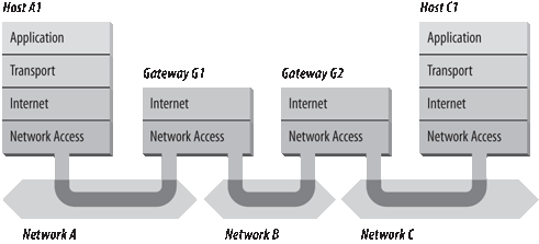
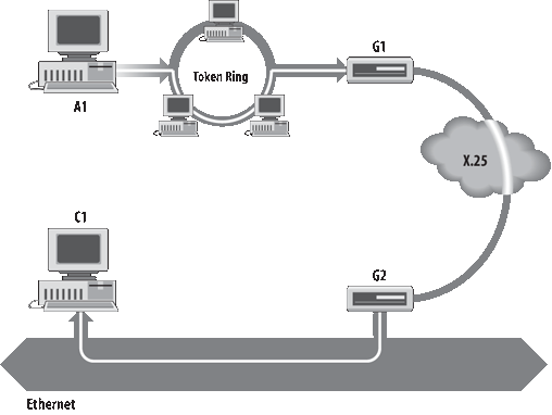
Figure 1-7 shows another view of routing. This figure emphasizes that the underlying physical networks a datagram travels through may be different and even incompatible. Host A1 on the fiber optic network routes the datagram through gateway G1 to reach host C1 on the Ethernet. Gateway G1 forwards the data through the frame relay network to gateway G2 for delivery to C1. The datagram traverses three physically different networks, but eventually arrives intact at C1.
As a datagram is routed through different networks, it may be necessary for the IP module in a gateway to divide the datagram into smaller pieces. A datagram received from one network may be too large to be transmitted in a single packet on a different network. This condition occurs only when a gateway interconnects dissimilar physical networks.
Each type of network has a maximum transmission unit (MTU), which is the largest packet that it can transfer. If the datagram received from one network is longer than the other network’s MTU, it is necessary to divide the datagram into smaller fragments for transmission. This process is called fragmentation . Think of a train delivering a load of steel. Each railway car can carry more steel than the trucks that will take it along the highway, so each railway car is unloaded onto many different trucks. In the same way that a railroad is physically different from a highway, an Ethernet is physically different from an X.25 network. IP must break an Ethernet’s relatively large packets into smaller packets before it can transmit them over an X.25 network.
The format of each fragment is the same as the format of any normal datagram. Word 2 in the header, as shown in Figure 1-5, contains information that identifies each datagram fragment and provides information about how to reassemble the fragments back into the original datagram. The Identification field identifies what datagram the fragment belongs to, and the Fragmentation Offset field tells what piece of the datagram this fragment is. The Flags field has a “More Fragments” bit that tells IP if it has assembled all of the datagram fragments.
When IP receives a datagram that is addressed to the local host, it must pass the data portion of the datagram to the correct Transport Layer protocol . This is done by using the protocol number from word 3 of the datagram header. Each Transport Layer protocol has a unique protocol number that identifies it to IP. Protocol numbers are discussed in Chapter 2.
You can see from this short overview that IP performs many important functions. Don’t expect to fully understand datagrams, gateways, routing, IP addresses, and all the other things that IP does from this short description. Each chapter adds more details about these topics.
An integral part of IP is the Internet Control Message Protocol (ICMP ) defined in RFC 792. This protocol is part of the Internet Layer and uses the IP datagram delivery facility to send its messages. ICMP sends messages that perform the following control, error reporting, and informational functions for TCP/IP:
- Flow control
When datagrams arrive too fast for processing, the destination host or an intermediate gateway sends an ICMP Source Quench Message back to the sender. This tells the source to stop sending datagrams temporarily so that the destination host can catch up.
- Detecting unreachable destinations
When a destination is unreachable, the system detecting the problem sends a Destination Unreachable Message to the datagram’s source. If the unreachable destination is a network or host, the message is sent by an intermediate gateway. But if the destination is an unreachable port, the destination host sends the message (more on ports in Chapter 2). The tracert command takes advantage of the Destination Unreachable Message to create its list of gateways along the route. Exactly how it does this is explained in Chapter 14.
- Redirecting routes
A gateway sends the ICMP Redirect Message to tell a host to use another gateway, presumably because the other gateway is a better choice. This message can be used only when the source host is on the same network as both gateways. To better understand this, refer to Figure 1-7. If a host on the frame relay network sent a datagram to G1, it would be possible for G1 to redirect that host to G2 because the host, G1, and G2 are all attached to the same network. On the other hand, if a host on the fiber optic network sent a datagram to G1, the host could not be redirected to use G2. This is because G2 is not attached to the fiber optic network.
- Checking remote hosts
A host can send the ICMP Echo Message to see if a remote system’s Internet Protocol is up and operational. When a system receives an echo message, it replies and sends the data from the packet back to the source host. The ping command uses this message.
IP Security (IPSec ) provides security services for IP datagrams. IPSec is not a single protocol. It is a security framework made up of several protocols. IPSec can provide both authentication services and data encryption. An overview of IPSec is found in RFC 2401, Security Architecture for the Internet Protocol.
IPSec requires each host to be authenticated, called endpoint authentication , before it sends the data. Windows Server 2003 supports host authentication using shared secret keys, public key certificates or Kerberos. (Active Directory can provide Kerberos authentication.) IPSec provides data authentication by using a hash-based message authentication code (HMAC). The HMAC verifies the source of the data and the data integrity. Windows Server 2003 supports HMAC MD5 (Message Digest 5), as described in RFC 2403, and HMAC SHA1 (Secure Hash Algorithm 1), as described in RFC 2404. IPSec can also provide encryption to ensure that the transmitted data is kept secret. Windows supports both the Data Encryption Standard (DES) and Triple DES (3DES) for data encryption.
IPSec uses two header formats to provide authentication and encryption security services. The Authentication Header (AH), which is described in RFC 2402, provides source and data authentication for all headers and data. The Encapsulating Security Payload (ESP ) header and trailer, which is described in RFC 2406, provides encryption services and authentication of the ESP header and the encrypted portion of the datagram.
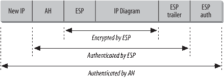
In addition to two header formats, IPSec runs in two different modes. Tunnel mode is used by secure routers passing data across an unsecured network, such as the Internet, and transport mode is used by end systems for end-to-end security. Tunnel mode provides protection for the complete original IP datagram. Transport mode provides protection for the upper layer data carried by the original datagram. Figure 1-8 shows an IPSec tunnel mode packet that contains both AH and ESP headers.
In tunnel mode, IPSec creates a new IP header to route the packet to a specific remote secure router. The destination address used for this header is the address specified on the Tunnel Setting tab when the IPSec properties are configured. (IPSec configuration is covered in Chapter 11.) In transport mode, the IP header from the original datagram begins the IPSec packet and the AH and ESP headers come between the original IP header and the data from the original datagram. In tunnel mode, the entire original datagram (headers and all) is the payload data field of the IPSec packet, and the new IP, AH and ESP headers are placed before the entire original datagram.
The AH contains half-a-dozen fields. However, it is the Sequence Number and the Authentication Data fields that provide the source authentication, data integrity checks and replay protection. The Authentication Data field contains an Integrity Check Value (ICV), which is either an HMAC MD5 or HMAC SHA1 value. The ICV provides a data integrity check of the entire IPSec packet, including the AH header itself. Only those fields in the IP header that by their nature change during transmission, are exempted from the ICV such as the Time-To-Live (TTL) field. Because the Sequence Number is included in the ICV, any attempt by an attacker to modify the Sequence Number is detected, thus providing protection against replay attacks. Finally, the ICV provides source authentication because only a source with the correct secret key can produce a valid HMAC MD5 or HMAC SHA1 value.
When the ESP protocol is used in tunnel mode, as it is in Figure 1-8, the complete, original IP header is encrypted and encapsulated in an ESP header and an ESP trailer. (In transport mode, the payload data field would only contain the data field from the original IP datagram.) The ESP header contains a Sequence Number used by the ESP protocol and information relating to the Security Association (SA) used for this encrypted communication. The trailer contains any padding required by the encryption method. The payload data and the ESP trailer are encrypted. The ESP header and everything before it (the new IP header and the AH in Figure 1-8) are sent as clear text.
The IPSec packet shown in Figure 1-8 concludes with ESP authentication data. This field contains an ICV calculation that authenticates the ESP header, trailer, and payload data. The reason that AH is frequently used with ESP is that AH authenticates the entire packet from the new IP header through and including the ESP authentication data field, which provides more complete coverage than the ESP authentication data.
Figure 1-8 shows IPSec running in tunnel mode to protect complete IP datagrams. IPSec can also be run in transport mode to protect the data received from the Transport Layer protocol. The Transport Layer is our next topic.
The protocol layer just above the Internet Layer is the Transport Layer. The two most important protocols in the Transport Layer are Transmission Control Protocol (TCP) and User Datagram Protocol (UDP). TCP provides reliable, connection-oriented data delivery service with end-to-end error detection and correction. UDP provides low-overhead, connectionless datagram delivery service. Both protocols deliver data between the Application Layer and the Internet Layer. Applications programmers can choose whichever service is more appropriate for their specific applications.
The User Datagram Protocol gives application programs direct access to a datagram delivery service, like the delivery service that IP provides. This allows applications to exchange messages over the network with a minimum of protocol overhead.
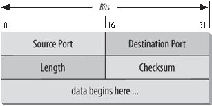
UDP is an unreliable, connectionless datagram protocol. As noted previously, “unreliable” means that there are no techniques in the protocol for verifying that the data reached the other end of the network correctly. UDP uses 16-bit Source Port and Destination Port numbers in word 1 of the message header, to deliver data to the correct applications process. Figure 1-9 shows the UDP message format.
Applications programmers choose UDP as a data transport service for a number of good reasons. If the amount of data being transmitted is small, the overhead of creating connections and ensuring reliable delivery may be greater than the work of retransmitting the entire data set. In this case, UDP is the most efficient choice for a Transport Layer protocol. Applications that fit a query-response model are also excellent candidates for using UDP. The response can be used as a positive acknowledgment to the query. If a response isn’t received within a certain time period, the application just sends another query. Still other applications provide their own techniques for reliable data delivery and don’t require service from the transport layer protocol. Imposing another layer of acknowledgment on any of these types of applications is inefficient.
Applications that require the transport protocol to provide reliable data delivery use TCP because it verifies that data is delivered across the network accurately and in the proper sequence. TCP is a reliable, connection-oriented, byte-stream protocol. Let’s look at each of the terms—reliable, connection-oriented, and byte-stream—in more detail.
TCP provides reliability with a mechanism called Positive Acknowledgment with Retransmission (PAR ). Simply stated, a system using PAR sends the data again, unless it hears from the remote system that the data has arrived. The unit of data exchanged between cooperating TCP modules is called a segment (see Figure 1-10). Each segment contains a checksum that the recipient uses to verify that the data is undamaged. If the data segment is received undamaged, the receiver sends a positive acknowledgment back to the sender. If the data segment is damaged, the receiver discards it. After an appropriate time-out period, the sending TCP module retransmits any segment for which no positive acknowledgment has been received.
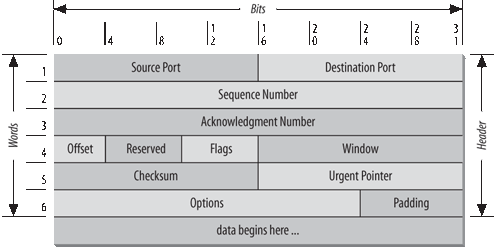
TCP is connection-oriented. It establishes a logical, end-to-end connection between the two communicating hosts. Control information, called a handshake , is exchanged between the two endpoints to establish a dialogue before data is transmitted. TCP indicates the control function of a segment by setting the appropriate bit in the Flags field in word 4 of the segment header.
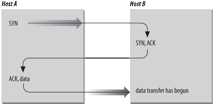
The type of handshake used by TCP is called a three-way handshake because three segments are exchanged. Figure 1-11 shows the simplest form of the three-way handshake. Host A begins the connection by sending host B a segment with the “Synchronize Sequence Numbers” (SYN) bit set. This segment tells host B that A wishes to set up a connection, and it tells B what Sequence Number host A will use as a starting number for its segments. (Sequence Numbers are used to keep data in the proper order.) Host B responds to A with a segment that has the “Acknowledgment” (ACK) and SYN bits set. B’s segment acknowledges the receipt of A’s segment, and informs A what Sequence Number host B will start with. Finally, host A sends a segment that acknowledges receipt of B’s segment, and transfers the first actual data.
After this exchange, host A’s TCP has positive evidence that the remote TCP is alive and ready to receive data. As soon as the connection is established, data can be transferred. When the cooperating modules have concluded the data transfers, they will exchange a three-way handshake with segments containing the “No more data from sender” bit (called the FIN bit) to close the connection. The end-to-end exchange of control data provides the logical connection between the two systems.
TCP views the data it sends as a continuous stream of bytes, not as independent packets. Therefore, TCP takes care to maintain the sequence in which bytes are sent and received. The Sequence Number and Acknowledgment Number fields in the TCP segment header keep track of the bytes.
The TCP standard does not require that each system start numbering bytes with any specific number; each system chooses the number it will use as a starting point. To keep track of the data stream correctly, each end of the connection must know the other end’s initial number. The two ends of the connection synchronize byte-numbering systems by exchanging SYN segments during the handshake. The Sequence Number field in the SYN segment contains the Initial Sequence Number (ISN), which is the starting point for the byte-numbering system. For security reasons, the ISN is a random number.
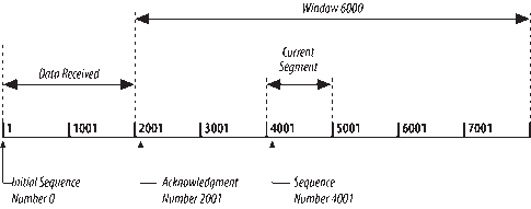
Each byte of data is numbered sequentially from the ISN, so the first real byte of data sent has a Sequence Number of ISN+1. The Sequence Number in the header of a data segment identifies the sequential position in the data stream of the first data byte in the segment. For example, if the first byte in the data stream is Sequence Number 1 (ISN=0) and 4,000 bytes of data have already been transferred, then the first byte of data in the current segment is byte 4001, and the Sequence Number would be 4001.
The Acknowledgment Segment (ACK) performs two functions: positive acknowledgment and flow control . The acknowledgment tells the sender how much data has been received and how much more the receiver can accept. The Acknowledgment Number is the Sequence Number of the next byte the receiver expects to receive. The standard does not require an individual acknowledgment for every packet. The Acknowledgment Number is a positive acknowledgment of all bytes up to that number. For example, if the first byte sent was numbered 1 and 2000 bytes have been successfully received, the Acknowledgment Number would be 2001.
The Window field contains the number of bytes the remote end is able to accept. If the receiver is capable of accepting 6,000 more bytes, the Window is 6000. The Window indicates to the sender that it can continue sending segments as long as the total number of bytes it sends is smaller than the Window of bytes the receiver can accept. The receiver controls the flow of bytes from the sender by changing the size of the Window. A zero Window tells the sender to cease transmission until it receives a nonzero Window value.
Figure 1-12 shows a TCP data stream that starts with an Initial Sequence Number of 0. The receiving system has received and acknowledged 2,000 bytes, so the current Acknowledgment Number is 2001. The receiver also has enough buffer space for another 6,000 bytes, so it has advertised a Window of 6000. The sender is currently sending a segment of 1,000 bytes starting with Sequence Number 4001. The sender has received no acknowledgment for the bytes from 2001 on, but continues sending data as long as it is within the Window. If the sender fills the Window and receives no acknowledgment of the data previously sent, it will, after an appropriate time-out, send the data again starting from the first unacknowledged byte. In Figure 1-12, retransmission would start from byte 2001 if no further acknowledgments are received. This procedure ensures that data is received reliably at the far end of the network.
TCP is also responsible for delivering data received from IP to the correct application. The application that the data is bound for is identified by a 16-bit number called the port number. The Source Port and Destination Port are contained in the first word of the segment header. Correctly passing data to and from the Application Layer is an important part of what the Transport Layer services do.
IPSec provides security in the IP layer. Security can also be provided in the Transport Layer . Transport Layer Security (TLS ) is an evolutionary outgrowth of the Secure Sockets Layer (SSL) protocol developed by Netscape for web security. TLS is an Internet standard based on SSL Version 3 (SSLv3). These protocols are very similar though not directly interoperable.
TLS is documented in RFC 2246, The TLS Protocol Version 1.0. TLS is composed of two sub-protocols: the Handshake Protocol negotiates connection parameters, and the Record Protocol moves the bulk of the data. Figure 1-13 shows a sample packet flow for a TLS handshake.
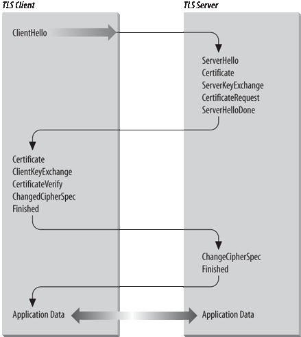
The client initiates the connection with a ClientHello message. The ClientHello lists the authentication methods, encryption methods and versions of TLS supported by the client. If the server accepts the connection request, it responds with a ServerHello message that defines the session identifier for the connection and selects security parameters for the session from the list of supported authentication and encryption methods advertised by the client.
At this point in Figure 1-13, the server sends a Certificate message that contains the server’s public key certificate. This message is optional, but is used when authentication is required for the handshake. If the Certificate message is not used, i.e., if the handshake will not be authenticated, a ServerKeyExchange message can be used in its place to provide key exchange information to the client. In fact, the optional ServerKeyExchange message can be used along with and following the Certificate message if an encryption technique is selected that requires more key exchange material than is provided by the Certificate.
SSL was originally developed to promote web-based commerce. As you might imagine with a protocol developed for electronic commerce, the server commonly sends the Certificate in order to authenticate itself. Before you send money to a remote web site, you want to make sure it is what it claims to be. For this reason, server authentication is common in SSL, which is the parent of TLS. It is much less common, however, for the client to be required to authenticate itself in an e-commerce environment. (The only thing most e-commerce sites want from a client is a valid credit card!) TLS is, however, intended for use in a wide variety of applications. Therefore, it is possible for the server to ask the client to authenticate itself. The server does this by sending the optional CertificateRequest message.
The sequence of messages from the server terminates with a ServerHelloDone message. As the paragraphs above make clear, there are several optional messages that the server can send after the ServerHello. The ServerHelloDone message lets the client know the server is finished sending.
The client responds to the ServerHelloDone message with a series of packets. If the server sent a CertificateRequest message, the client responds by sending a Certificate message. If the client does not have a valid certificate, it sends an empty message. When the server receives an empty Certificate message, it may terminate the session. Often, however, the session continues and it is up to the application to decide how to treat an unauthenticated client.
The client then sends the ClientKeyExchange message, which contains key exchange data. This message is not optional. It is always sent.
If the client sent a Certificate message that contained a valid public key certificate, the client may also send a CertificateVerify message that contains a digest of all handshake messages sent and received by the client starting from the ClientHello and going on through to the ClientKeyExchange. The server can use the client’s public key certificate to verify the digest and thus ensure that the client and server have both seen exactly the same messages.
Next, the client sends a ChangeCipherSpec message to switch to the encryption technique negotiated by the handshake. The messages that follow and the bulk data transmission are all encrypted using the negotiated technique. Finally, the client sends a Finished message. The server responds with its own ChangeCipherSpec and Finished messages and the encrypted data stream starts to flow.
TLS is generally invoked by applications, such as a web program or a mail delivery program, when they need a secure connection. The Application Layer is discussed next.
At the top of the TCP/IP protocol architecture is the Application Layer. This layer includes all processes that use the Transport Layer protocols to deliver data. There are many applications protocols. Most of these protocols provide user services, and new services are always being added to this layer.
Some widely known and implemented applications protocols follow:
- Telnet
The Network Terminal Protocol provides remote login over the network.
- FTP
The File Transfer Protocol is used for interactive file transfer.
- SMTP
The Simple Mail Transfer Protocol delivers electronic mail.
- HTTP
The Hypertext Transfer Protocol delivers web pages over the network.
While HTTP, FTP, SMTP, and Telnet are widely implemented TCP/IP applications that provide services directly to end users, you will work with other applications that primarily provide services from one host to another. Examples of these types of TCP/IP applications follow:
- Domain Name System (DNS)
Also called name service, this application maps IP addresses to the names assigned to network devices. DNS is discussed in detail in Chapter 6.
- Dynamic Host Configuration Protocol (DHCP)
This protocol is used to automatically configure networked computers. DHCP is covered in Chapter 5.
Some protocols, such as Telnet and FTP, can only be used if the user has some knowledge of the network. Other protocols, like DHCP, run without the user even knowing they exist. As network administrator, you are aware of all these applications and all the protocols in the other TCP/IP layers. And you’re responsible for configuring them for your Windows Server.
This chapter discussed the structure of TCP/IP, the protocol suite upon which the Internet is built. TCP/IP is a hierarchy of four layers: Applications, Transport, Internet, and Network Access. This chapter examined the function of each of these layers. The next chapter looks at how the IP datagram moves through a network when data is delivered between hosts.
[*] During the 1980s, ARPA, which is part of the U.S. Department of Defense, was called Defense Advanced Research Projects Agency (DARPA). Whether it is known as ARPA or DARPA, the agency and its mission of funding advanced research has remained the same.
[*] Experimental versions of IP using version numbers 0 to 3 were proposed in 1977 and 1978, but were superceded by IPv4 in August 1979.
[*] In current terminology, a gateway moves data between different protocols and a router moves data between different networks. So a system that moves mail between TCP/IP and X.400 is a gateway, but a traditional IP gateway is a router.
Get Windows Server 2003 Network Administration now with the O’Reilly learning platform.
O’Reilly members experience books, live events, courses curated by job role, and more from O’Reilly and nearly 200 top publishers.

