11.5 PROJECT 11.5 – LCD Dice
In this project, two dice numbers are displayed on the LCD when the user presses a button called STRT. The text ‘Good Luck’ is displayed in the first row of the LCD. The two dice numbers are displayed in the second row in the following format (assuming the numbers are 4 and 6):
![]()
11.5.1 Block Diagram
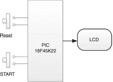
The block diagram of the project is shown in Figure 11.17.
Figure 11.17 Block diagram of the project

11.5.2 Circuit Diagram
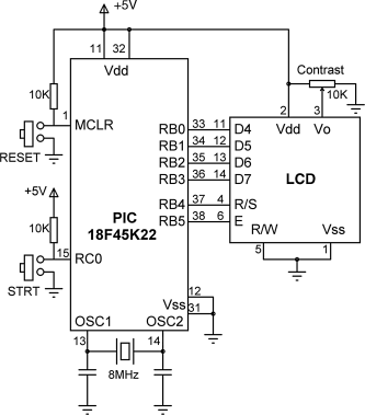
The circuit diagram of the project is shown in Figure 11.18. The LCD is connected to PORT B, as in the earlier projects. The STRT button is connected to pin RC0. This pin is normally at logic 1 and goes to logic 0 when the button is pressed. The project is based on a PIC18F45K22 type microcontroller with an 8 MHz crystal clock, although most other PIC microcontrollers can also be used.
Figure 11.18 Circuit diagram of the project

The connections between the microcontroller and the LCD are as follows:
| LCD Pin | Microcontroller Pin |
| D4 | RB0 |
| D5 | RB1 |
| D6 | RB2 |
| D7 | RB3 |
| R/S | RB4 |
| E | RB5 |
The contrast of the LCD is controlled by connecting a 10 KB potentiometer to pin 3 of the LCD. The microcontroller is Reset using an external push-button. ...
Get Using LEDs, LCDs and GLCDs in Microcontroller Projects now with the O’Reilly learning platform.
O’Reilly members experience books, live events, courses curated by job role, and more from O’Reilly and nearly 200 top publishers.

