Deployment
The most important aspect of deployment diagrams is conveying the relationship between artifacts and the node(s) they execute on. When you associate an artifact with a deployment target
(anything that can host an artifact, such as a device or execution environment), you deploy that artifact. For example, you may have an artifact named ccvalidator.jar that represents the credit card validation subsystem of an application. When you say ccvalidator.jar executes on the node Appserver1, you have deployed the artifact.
Deployment Representation
UML provides several ways to show deployment. You may show artifact deployment by simply drawing an artifact in the hosting node's cube. Figure 6-13 shows an artifact named ccvalidator.jar deployed to the device Appserver1.
UML also allows you to show deployment using a dashed line with an open arrow (dependency) pointing from the artifact to the deployment target. You should stereotype this line with the keyword «deploy». Figure 6-14 shows the same deployment relationship as Figure 6-13, but uses the dependency notation.
Finally, you may show deployment by simply listing deployed artifacts in a compartment in the deployment target's classifier. This notation is particularly useful if you have a lot of artifacts deployed to a single node. Figure 6-15 shows an execution environment with several deployed artifacts.
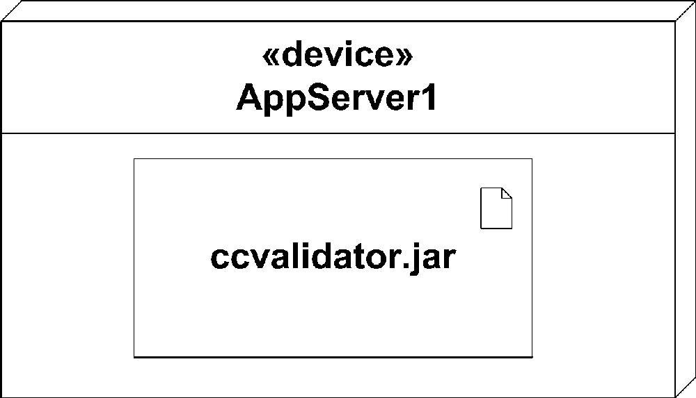
Figure 6-13. An artifact ...
Get UML 2.0 in a Nutshell now with the O’Reilly learning platform.
O’Reilly members experience books, live events, courses curated by job role, and more from O’Reilly and nearly 200 top publishers.

