Chapter 5. Component Diagrams
When modeling large software systems it is common to break the software into manageable subsystems. UML provides the component classifier for exactly this purpose. A component is a replaceable, executable piece of a larger system whose implementation details are hidden. The functionality provided by a component is specified by a set of provided interfaces that the component realizes (see "Black-Box View"). In addition to providing interfaces, a component may require interfaces in order to function. These are called required interfaces.
The functionality of a component's provided interfaces is implemented with one or more internal classifiers. These are typically classes but can be other components (see "White-Box View"). Components should be designed to be reused, with dependencies on external interfaces, strong encapsulation, and high cohesion.
Components
In UML 2.0, you represent a component with the classifier rectangle stereotyped as «component». Like other classifiers, if the details of the component aren't shown, you place the name of the component in the center of the rectangle. Optionally, you may show the component icon (a rectangle with two smaller rectangles on the left side) in the upper-right corner. Figure 5-1 shows a simple component.
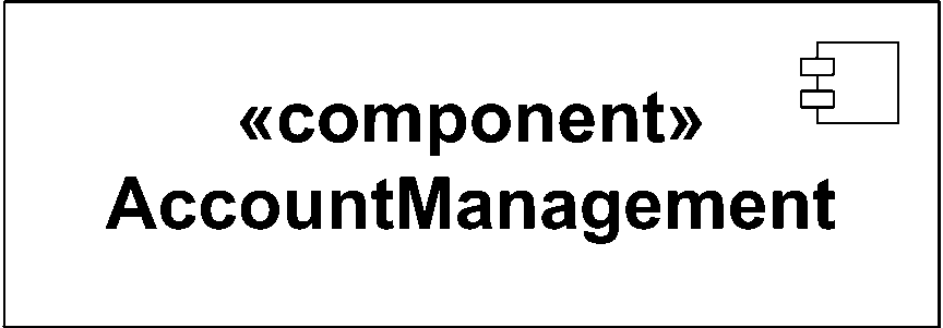
Figure 5-1. A simple component
Warning
The representation for a component has changed from previous versions ...
Get UML 2.0 in a Nutshell now with the O’Reilly learning platform.
O’Reilly members experience books, live events, courses curated by job role, and more from O’Reilly and nearly 200 top publishers.

