APPENDIX DAirbus 320 Class Case Study
All computations carried out here follow the book instructions. The results are not from Airbus and they are not responsible for the figures given here. They are used only to substantiate the book methodology to get some confidence. Industry drag data are not available, but at the end, check whether the payload‐range matches with the published data. We will investigate the case at long‐range cruise (LRC) speed of Mach 0.75, and altitude of 36,089 ft.
D.1 Dimensions
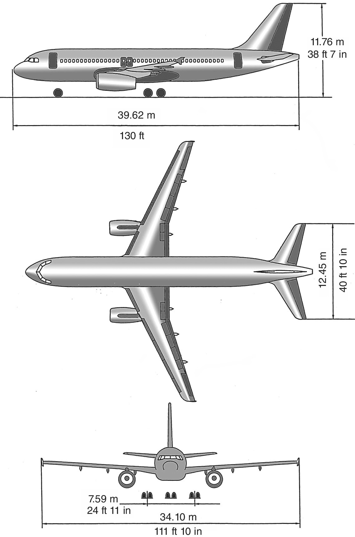
See Figure D.1 for the configuration and dimensions of the Airbus 320.
- Fuselage length = 123.16 ft (scaled measurements differ slightly from the drawings).
- Fuselage width = 13.1 ft.
- Fuselage depth = 13 ft.
- Wing reference area (trapezoidal part only) = 1202.5 ft2, add yehudi area = 118.8 ft2.
- Span = 11.85 ft, MACwing = 11.64 ft, AR = 9.37, Λ¼ = 25°, CR = 16.5 ft, λ = 0.3.
- H‐tail reference area = 330.5 ft2, MACH‐tail = 8.63 ft.
- V‐tail reference area = 235.6 ft2, MACV‐tail = 13.02 ft.
- Nacelle length = 17.28 ft, maximum diameter = 6.95 ft.
- Pylon = to measure from the drawing.

Figure D.1 Airbus 320 three‐view with major dimensions
(courtesy of Airbus)
Reynolds number per foot is given by:
D.2 Drag Computation
D.2.1 Fuselage
Table D.1 gives the basic average 2D flat ...
Get Theory and Practice of Aircraft Performance now with the O’Reilly learning platform.
O’Reilly members experience books, live events, courses curated by job role, and more from O’Reilly and nearly 200 top publishers.

