16.5 ADDER-SUBTRACTOR
An adder-subtractor based on Algorithm 16.4 will now be synthesized. It is made up of four parts, namely, alignment, addition, normalization, and rounding.
16.5.1 Alignment
The alignment circuit implements the three first lines of the algorithm, that is,
if operation=1 then sign2:=1 – sign2; end if;
if e1<e2 then swap(sign1, sign2); swap(s1, s2); swap (e1, e2);
end if;
e:=e1; s2:=s2/B**(e1-e2); sign:=sign1;
An example of the implementation is shown in Figure 16.1. The principal component is a shifter.
Given a (2.p + 4)-component vector
![]()
the shifter generates a (2.p + 4)-component output vector
![]()
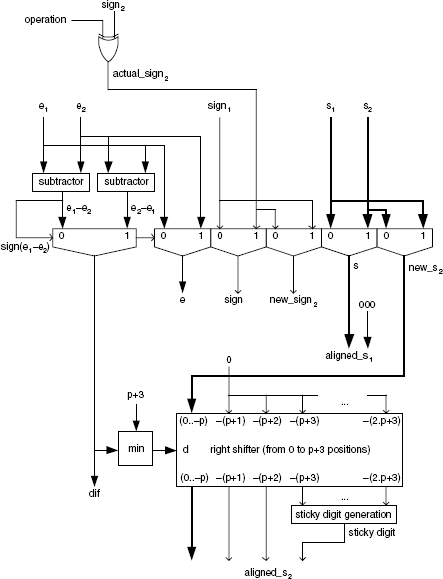
Figure 16.1 Alignment circuit.
The sticky-digit circuit generates an output value 1 if at least one of its inputs is positive. If B = 2, the sticky-digit circuit is an OR circuit. Observe that if e1 − e2 is equal to p + 3, then the shifter output is equal to
[0 0..0 new_s2(0) new_s2(-1)..new_s2(-p)].
Taking into account that new_s2 is either s1 or s2, i.e. a normalized significand, new_s2(0) is positive. Thus the sticky digit is equal to 1 and the value of aligned_s2 is
[0 0..0 0 1].
If e1 − e2 were greater than p + 3, the value of aligned_s2 should be the same, so ...
Get Synthesis of Arithmetic Circuits: FPGA, ASIC and Embedded Systems now with the O’Reilly learning platform.
O’Reilly members experience books, live events, courses curated by job role, and more from O’Reilly and nearly 200 top publishers.

