13.2 INTEGERS
13.2.1 Base-2 Nonrestoring Divider
Let Y be an n-bit positive number and X an integer belonging to the range − Y ≤ X < Y, so that it can be represented as an (n + 1)-bit 2's complement number. The circuit corresponding to the nonrestoring algorithm 6.6 (with q(i) substituted by q(p − i) in order that the least significant bit of q be q(0)) is shown in Figures 13.6 (basic cell), 13.7 (divider structure, combinational and sequential implementations), and 13.8 (correction circuit).
The cost and computation time of the corresponding divider are
![]()
and
![]()
Examples 13.4 (Complete VHDL source code available.) Generate a VHDL model of a generic base-2 nonrestoring divider (Figures 13.6, 13.7, and 13.8):
entity nonr_cell is
port (
  a: in STD_LOGIC_VECTOR (N-1 downto 0);
  b: in STD_LOGIC_VECTOR (N-1 downto 0);
  q: in STD_LOGIC;
  r: out STD_LOGIC_VECTOR (N downto 0)
);
end nonr_cell;

architecture nr_cel_arch of nonr_cell is
signal a_by_2: STD_LOGIC_VECTOR (N downto 0);
begin
a_by_2<=a(N-1 downto 0)&‘0’;
adder_subtracter: process (a_by_2,b,q)
begin
  if q=‘1’ then r<=a_by_2+b;
  else r<=a_by_2 - b;
  end if;
end process;
end nr_cel_arch;
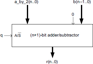
Figure 13.6 Nonrestoring divider: basic cell.
Figure 13.7 ...
Get Synthesis of Arithmetic Circuits: FPGA, ASIC and Embedded Systems now with the O’Reilly learning platform.
O’Reilly members experience books, live events, courses curated by job role, and more from O’Reilly and nearly 200 top publishers.

