10.3 PIPELINE
A very useful implementation technique, especially for signal processing circuits, is pipelining.
Example 10.5 Consider again a 128-bit adder made up of four 32-bit adders. A parallel (combinational) implementation is described in Figure 10.6. The computation time (latency) of the circuit is roughly equal to 4.T, where T is the computation time of a 32-bit adder, so that the maximum sample rate of the input operands x and y is equal to 1/(4.T). The corresponding pipelined circuit is shown in Figure 10.7: a register is inserted between the computation resources assigned to successive cycles, in such a way that a new addition can be started as soon as the first cycle of the preceding addition has been completed, that is, every T seconds. In this way the latency is still equal to 4.T. Nevertheless, the sample rate is equal to 1/T instead of 1 /(4.T).
Comments 10.1
- The extra cost of the pipeline registers could appear to be prohibitive. Nevertheless, in many data processing systems there is a continuous flow of new operands so that dynamic latches, instead of static ones, can be used, and an n-bit register practically reduces to n pass transistors (full-custom implementation). Latchless pipelining techniques have also been reported ([FLY1997]).
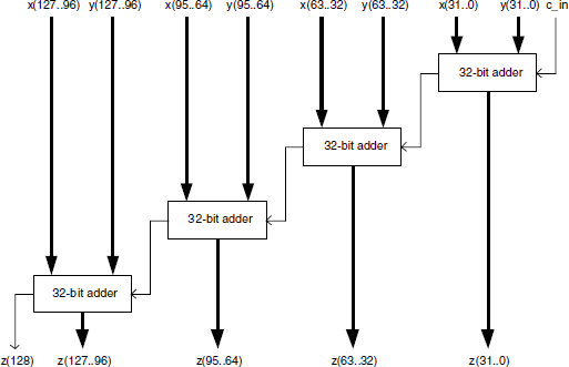
Figure 10.6 Parallel 128-bit adder.
- The insertion of pipeline registers also has a positive effect on the power consumption: ...
Get Synthesis of Arithmetic Circuits: FPGA, ASIC and Embedded Systems now with the O’Reilly learning platform.
O’Reilly members experience books, live events, courses curated by job role, and more from O’Reilly and nearly 200 top publishers.

