11.3 Directional Coupler
As the first illustration of the use of the coupled mode theory, we shall consider the directional coupler, an important device used for the switching and splitting of power needed in optical communications [1–7]. In Section 3.1, we shall consider a simpler situation, in which the two coupled waveguides are identical, satisfying the phase-matched condition. In Section 3.2, the theory will be generalized for the non-phase-matched condition.
11.3.1 Phase-matched Directional Coupler
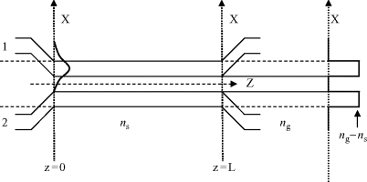
Figure 11.2a shows a schematic of a single-mode guided wave directional coupler, in which two identical waveguides of RI, ng, surrounded by a dielectric of RI, ns, are brought close to each other over a coupling distance L. As illustrated in Figure 11.2, the unperturbed field profile f1(x) associated with the mode incident in waveguide 1 indicates that there is negligible coupling between the waveguides for z < 0 and z > L. In Figure 11.2b, the changes in RI in the guide regions are shown. When the mode is incident in waveguide 2, the distribution of the field and RI will have a similar variation.
Figure 11.2 (a) Schematic diagram of a directional coupler, showing the intensity profile of the radiation input into guide 1 at z = 0; and (b) plot of n0(x), f1(x), and Δn(x) for the mode incident in waveguide 1 of (a).

Since we are assuming the two waveguides to be identical, their ...
Get Silicon Photonics: Fundamentals and Devices now with the O’Reilly learning platform.
O’Reilly members experience books, live events, courses curated by job role, and more from O’Reilly and nearly 200 top publishers.

