6
Time-Domain Reflectometry Analysis
Time-domain reflectometry (TDR) consists of sending an impulse or an echelon to a circuit and analyzing the signal reflected. It is then possible to deduce from this the position of impedance breaks or defects as well as the characteristics of corresponding discontinuities (resistive, capacitive or inductive).
6.1. Principle of TDR
The signal used in TDR can be a short-duration impulse or an echelon (rising front or falling front).
Figure 6.1. Typical signals used in time-domain reflectometry
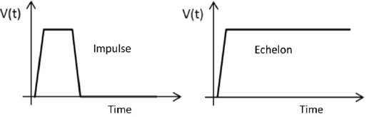
An impulse is generally used when the propagation time is large enough in relation to the duration of the impulse for there to be no superimposition with the reflected signal. This is the typical case with computer network analyzers. An echelon is generally used in TDR applied to PCB or integrated circuits. The propagation times are of the same order of grandeur as rise time, and analysis requires being able to control the degradation of rise time in connectors and interfaces. If propagation parameters (speed, impedance) are dependent on frequency, the impulse propagates with strain. This strain generally accompanies an increase in rise time, corresponding to low-pass filter as discussed in Chapter 1.
6.2. Reflection and transmission of voltage
Signals propagating in cables and circuits can generally be represented by a voltage V(t) and a current I(t). Let ...
Get Signal Integrity: From High Speed to Radiofrequency Applications now with the O’Reilly learning platform.
O’Reilly members experience books, live events, courses curated by job role, and more from O’Reilly and nearly 200 top publishers.

