4.14 Class D Full-Bridge RF Power Amplifier
4.14.1 Currents, Voltages, and Powers
The circuit of a Class D full-bridge with a series-resonant amplifier is shown in Fig. 4.32. It consists of four controllable switches and a series-resonant circuit. Current and voltage waveforms in the amplifier are shown in Fig. 4.33. Notice that the voltage at the input of the resonant circuit is twice as high as that of the half-bridge amplifier. The average resistance of the on-resistances of power MOSFETs is ![]() . The total parasitic resistance is represented by
. The total parasitic resistance is represented by
which yields the overall resistance
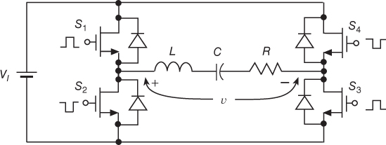
Figure 4.32 Full-bridge Class D power amplifier with a series-resonant circuit.
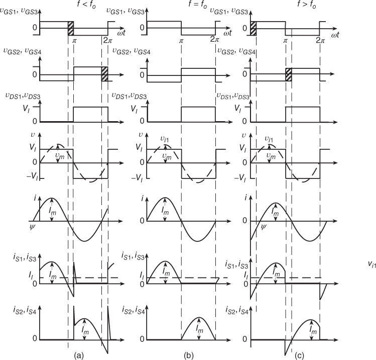
Figure 4.33 Waveforms in the Class D full-bridge power amplifier. (a) For  . (b) For
  . (c) For .
When the switches ...
Get RF Power Amplifier, 2nd Edition now with the O’Reilly learning platform.
O’Reilly members experience books, live events, courses curated by job role, and more from O’Reilly and nearly 200 top publishers.

