6.3 Impedance Matching
A transmission line with a characteristic impedance Z0 that is terminated by a load impedance ZA shows no reflections at the end of the line if characteristic impedance and load impedance are equal Z0 = ZA (see Section 3.1.8). Furthermore, in order to obtain maximum power from a source with an internal impedance ZI the load impedance ZA should be the conjugate-complex value of the internal impedance ![]() (see Section 5.4.2).
(see Section 5.4.2).
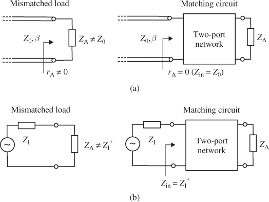
If the load impedance is mismatched, special two-port networks (matching circuits) can be designed to transform the actual load impedance to the required input impedance Zin (see Figure 6.11).
Figure 6.11 Two-port matching networks for (a) matched (non-reflective) line termination and (b) maximum power transfer.
Low-loss matching networks can be constructed by using reactive components (capacitors and inductors) or transmission lines. Since these components exhibit frequency dependent behaviour the desired impedance transformation is limited to a certain frequency range.
We will start by looking at resistive load impedances (ZA = RA) and resistive target impedances (Zin = RI). Later on we will expand our view and include universal complex load impedances. Even today the classical Smith chart is a valuable tool when designing matching circuits. ...
Get RF and Microwave Engineering: Fundamentals of Wireless Communications now with the O’Reilly learning platform.
O’Reilly members experience books, live events, courses curated by job role, and more from O’Reilly and nearly 200 top publishers.

